MAN B&W
18.04
Page 6 of 7
MAN Diesel
MAN B&W MC/MCC engines
198 62 364.2
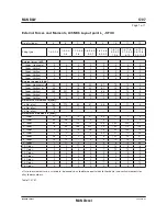
Slow down for UMS – Class and MAN Diesel requirements
Table 18.04.03: Slow down functions for UMS
A
B
S
B
V
C
C
S
D
N
V
G
L
K
R
L
R
N
K
R
IN
A
R
S
IA
C
S
M
A
N D
ie
se
l
Sensor and
function
Point of location
1
1
1
1
1
1
1
1
1
1
1
1 TE 8106 YH Thrust bearing segment
1
1
1 1* 1
1
1
1
1
1
1
1 PT 8108 YL Lubricating oil inlet to main engine
1
1
TE 8112 YH Lubricating oil inlet to main engine
1
1
1
1
1
1
1
1
1
1
1 TE 811 YH Piston cooling oil outlet/cylinder
1
1
1
1
1
1
1
1
1
1
1 FS 8114 YL Piston cooling oil outlet/cylinder
1 TE 812 YH Main bearing oil outlet temperature/main bearing
(Only MC types 42-26)
1 XC 8126 YH Bearing wear (K98MC6/7 and all MC-C types)
1
1
1
1
1
1
1
1
1
1
1 PT 8401 YL Jacket cooling water inlet
1
1
1
1
1
1
1
1
1
1
1
1 TE 8408 YH Jacket cooling water outlet, cylinder/cylinder
1
1
1
TE 8609 YH Scavenge air receiver
1
1
1
1
1
1
1
1
1
1
1
1 TE 8610 YH Scavenge air box fire-alarm, cylinder/cylinder
1
1
1
TC 8701 YH Exhaust gas before turbocharger/turbocharger
1
1
1
1
1
1
1
1
1
1
1 TC 8702 YH Exhaust gas after exhaust valve, cylinder/cylinder
1
1
TC 8702 YH Exhaust gas after exhaust valve, cylinder/cylinder,
deviation from average
1 WT 8812 YH Axial vibration monitor 2)
1
1
1*
1
1
1
1
1
1
1 XS 881 YH Oil mist in crankcase/cylinder
1 Indicates that the sensor is required.
The sensors in the MAN Diesel column are included for Unattended Machinery Spaces (UMS), option: 4 75 127.
The sensor identification codes and functions are listed in Table 18.07.01.
The tables are liable to change without notice, and are subject to latest class requirements.
2) Required for: K-MC-C6/7 and K98MC6/7 engines with 11 and 14 cylinders.
S-MC-C7/8 and L-MC-C7/8 engines with 5 and 6 cylinders.
(For 9-12 cylinder S42MC7, L5MC6, and S26MC6 data is available on request).
Select one of the alternatives
* Or shut down
Or alarm for low flow
* Or shut down
Or alarm for overheating of main, crank and crosshead bearings, option: 4 75 14.
See also Table 18.04.04: Shut down functions for AMS and UMS
Summary of Contents for B&W L35MC6-TII
Page 4: ......
Page 10: ......
Page 18: ......
Page 19: ...MAN B W MAN Diesel Engine Design 1 ...
Page 20: ......
Page 35: ...MAN B W MAN Diesel Engine Layout and Load Diagrams SFOC 2 ...
Page 36: ......
Page 52: ......
Page 64: ......
Page 65: ...MAN B W MAN Diesel Turbocharger Selection Exhaust Gas By pass 3 ...
Page 66: ......
Page 72: ......
Page 73: ...MAN B W MAN Diesel Electricity Production 4 ...
Page 74: ......
Page 95: ...MAN B W MAN Diesel Installation Aspects 5 ...
Page 96: ......
Page 132: ......
Page 146: ......
Page 147: ...MAN B W MAN Diesel List of Capacities Pumps Coolers Exhaust Gas 6 ...
Page 148: ......
Page 171: ...MAN B W MAN Diesel Fuel 7 ...
Page 172: ......
Page 186: ......
Page 187: ...MAN B W MAN Diesel Lubricating Oil 8 ...
Page 188: ......
Page 203: ...MAN B W MAN Diesel Cylinder Lubrication 9 ...
Page 204: ......
Page 213: ...MAN B W MAN Diesel Piston Rod Stuffing Box Drain Oil 10 ...
Page 214: ......
Page 215: ......
Page 217: ...MAN B W MAN Diesel Central Cooling Water System 11 ...
Page 218: ......
Page 223: ...MAN B W MAN Diesel Seawater Cooling System 12 ...
Page 224: ......
Page 234: ......
Page 235: ...MAN B W MAN Diesel Starting and Control Air 13 ...
Page 236: ......
Page 242: ......
Page 243: ...MAN B W MAN Diesel Scavenge Air 14 ...
Page 244: ......
Page 256: ......
Page 257: ...MAN B W MAN Diesel Exhaust Gas 15 ...
Page 258: ......
Page 272: ......
Page 273: ...MAN B W MAN Diesel Engine Control System 16 ...
Page 274: ......
Page 289: ...MAN B W MAN Diesel Vibration Aspects 17 ...
Page 290: ......
Page 304: ......
Page 305: ...MAN B W MAN Diesel Monitoring Systems and Instrumentation 18 ...
Page 306: ......
Page 328: ......
Page 329: ...MAN B W MAN Diesel Dispatch Pattern Testing Spares and Tools 19 ...
Page 330: ......
Page 360: ......
Page 361: ...MAN B W MAN Diesel Project Suppport and Documentation 20 ...
Page 362: ......
Page 371: ...MAN B W MAN Diesel Appendix A ...
Page 372: ......

