MAN B&W
2.04
Page 1 of 10
MAN Diesel
198 69 94-7.1
MAN B&W MC/MC-C-TII engines
Engine Layout and Load Diagram
Engine Layout Diagram
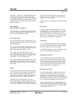
An engine’s layout diagram is limited by two con-
stant mean effective pressure (mep) lines L
1
– L
3
and L
2
– L
4
, and by two constant engine speed
lines L
1
– L
2
and L
3
– L
4
. The L
1
point refers to the
engine’s nominal maximum continuous rating, see
Fig. 2.04.01.
In the layout area, the engine’s specified SMCR
point M can be set freely to suit the ship’s de-
mand for propeller power and speed.
On the horizontal axis and on the vertical axis the
engine speed and the engine power are shown,
respectively, on percentage scales. The scales
are logarithmic, which means that, in this diagram,
power function curves like propeller curves (3rd
power), constant mean effective pressure curves
(1st power) and constant ship speed curves (0.15
to 0.30 power) are straight lines.
Specified maximum continuous rating (M)
Based on the propulsion and engine running
points, found previously, the layout diagram of a
relevant main engine can be drawnin. The SMCR
point (M) must be inside the limitation lines of the
layout diagram; if it is not, the propeller speed
must be changed or another main engine type
chosen.
Continuous service rating (S)
The continuous service rating is the power need-
ed in service - including the specified sea margin
and heavy/light running factor of the propeller
- at which the engine is to operate, and point S
is identical to the service propulsion point (SP)
unless a main engine driven shaft generator is
installed.
Optimising point (O)
The optimising point O is the rating at which the
turbocharger is matched, and at which the engine
timing and compression ratio are adjusted. Point
M normally coincides with point O.
The optimising point O is placed on line 1 of the
load diagram, see Fig. 2.04.02, and for technical
reasons the optimised power always has to be
equal to 100% of point M’s power.
L
1
L
2
L
3
L
4
Speed
Power
O=M
S
1
Fig. 2.04.01: Engine layout diagram
178 60 85-8.0
Summary of Contents for B&W L35MC6-TII
Page 4: ......
Page 10: ......
Page 18: ......
Page 19: ...MAN B W MAN Diesel Engine Design 1 ...
Page 20: ......
Page 35: ...MAN B W MAN Diesel Engine Layout and Load Diagrams SFOC 2 ...
Page 36: ......
Page 52: ......
Page 64: ......
Page 65: ...MAN B W MAN Diesel Turbocharger Selection Exhaust Gas By pass 3 ...
Page 66: ......
Page 72: ......
Page 73: ...MAN B W MAN Diesel Electricity Production 4 ...
Page 74: ......
Page 95: ...MAN B W MAN Diesel Installation Aspects 5 ...
Page 96: ......
Page 132: ......
Page 146: ......
Page 147: ...MAN B W MAN Diesel List of Capacities Pumps Coolers Exhaust Gas 6 ...
Page 148: ......
Page 171: ...MAN B W MAN Diesel Fuel 7 ...
Page 172: ......
Page 186: ......
Page 187: ...MAN B W MAN Diesel Lubricating Oil 8 ...
Page 188: ......
Page 203: ...MAN B W MAN Diesel Cylinder Lubrication 9 ...
Page 204: ......
Page 213: ...MAN B W MAN Diesel Piston Rod Stuffing Box Drain Oil 10 ...
Page 214: ......
Page 215: ......
Page 217: ...MAN B W MAN Diesel Central Cooling Water System 11 ...
Page 218: ......
Page 223: ...MAN B W MAN Diesel Seawater Cooling System 12 ...
Page 224: ......
Page 234: ......
Page 235: ...MAN B W MAN Diesel Starting and Control Air 13 ...
Page 236: ......
Page 242: ......
Page 243: ...MAN B W MAN Diesel Scavenge Air 14 ...
Page 244: ......
Page 256: ......
Page 257: ...MAN B W MAN Diesel Exhaust Gas 15 ...
Page 258: ......
Page 272: ......
Page 273: ...MAN B W MAN Diesel Engine Control System 16 ...
Page 274: ......
Page 289: ...MAN B W MAN Diesel Vibration Aspects 17 ...
Page 290: ......
Page 304: ......
Page 305: ...MAN B W MAN Diesel Monitoring Systems and Instrumentation 18 ...
Page 306: ......
Page 328: ......
Page 329: ...MAN B W MAN Diesel Dispatch Pattern Testing Spares and Tools 19 ...
Page 330: ......
Page 360: ......
Page 361: ...MAN B W MAN Diesel Project Suppport and Documentation 20 ...
Page 362: ......
Page 371: ...MAN B W MAN Diesel Appendix A ...
Page 372: ......


