MAN B&W
2.04
Page 5 of 10
MAN Diesel
198 69 94-7.1
MAN B&W MC/MC-C-TII engines
80
100 105
85
55
90
95
60
Engine speed, % A
A 100% reference point
M Specified engine MCR
O Optimising point
Engine shaft power, % A
Heavy
running
operation
Normal
operation
50
70
80
90
100
40
110
60
110 115 120
L1
A=O=M
L2
5%
L3
L4
70
75
65
Normal load
diagram area
Extended light
running area
2
1
5
7
6
3
3
4
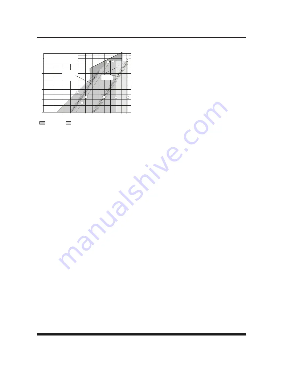
Line 1: Propeller curve through optimising point (O)
layout curve for engine
Line 2: Heavy propeller curve
fouled hull and heavy seas
Line 3: Speed limit
Line 3’:
Extended speed limit, provided torsional vibration
conditions permit
Line 4: Torque/speed limit
Line 5: Mean effective pressure limit
Line 6: Increased light running propeller curve
clean hull and calm weather
layout curve for propeller
Line 7: Power limit for continuous running
178 60 94-2.0
Fig. 2.04.03: Extended load diagram for speed derated
engine with increased light running
Examples of the use of the Load Diagram
In the following, some examples are illustrating
the flexibility of the layout and load diagrams.
• Example 1 shows how to place the load dia-
gram for an engine without a shaft generator
coupled to a fixed pitch propeller.
• Example 2 comprises diagrams for the same
configuration, here with the optimising point on
the left of the heavy running propeller curve (2),
providing an extra engine margin for heavy run-
ning, similar to the case in Fig. 2.04.03.
• Example 3 shows the same layout for an engine
with a fixed pitch propeller (Example 1), but with
a shaft generator.
• Example 4 is a special case of example 3, where
the specified MCR is placed near the top of the
layout diagram.
In this case, the shaft generator is cut off, and
the gensets used when the engine runs at spec-
ified MCR. This makes it possible to choose a
smaller engine with a lower power output.
• Example 5 shows diagrams for an engine cou-
pled to a controllable pitch propeller, with or
without a shaft generator, (constant speed or
combinator curve operation).
For a specific project, the layout diagram for the
actual project shown later in this chapter may be
used for drawing of the actual load diagram.
Summary of Contents for B&W L35MC6-TII
Page 4: ......
Page 10: ......
Page 18: ......
Page 19: ...MAN B W MAN Diesel Engine Design 1 ...
Page 20: ......
Page 35: ...MAN B W MAN Diesel Engine Layout and Load Diagrams SFOC 2 ...
Page 36: ......
Page 52: ......
Page 64: ......
Page 65: ...MAN B W MAN Diesel Turbocharger Selection Exhaust Gas By pass 3 ...
Page 66: ......
Page 72: ......
Page 73: ...MAN B W MAN Diesel Electricity Production 4 ...
Page 74: ......
Page 95: ...MAN B W MAN Diesel Installation Aspects 5 ...
Page 96: ......
Page 132: ......
Page 146: ......
Page 147: ...MAN B W MAN Diesel List of Capacities Pumps Coolers Exhaust Gas 6 ...
Page 148: ......
Page 171: ...MAN B W MAN Diesel Fuel 7 ...
Page 172: ......
Page 186: ......
Page 187: ...MAN B W MAN Diesel Lubricating Oil 8 ...
Page 188: ......
Page 203: ...MAN B W MAN Diesel Cylinder Lubrication 9 ...
Page 204: ......
Page 213: ...MAN B W MAN Diesel Piston Rod Stuffing Box Drain Oil 10 ...
Page 214: ......
Page 215: ......
Page 217: ...MAN B W MAN Diesel Central Cooling Water System 11 ...
Page 218: ......
Page 223: ...MAN B W MAN Diesel Seawater Cooling System 12 ...
Page 224: ......
Page 234: ......
Page 235: ...MAN B W MAN Diesel Starting and Control Air 13 ...
Page 236: ......
Page 242: ......
Page 243: ...MAN B W MAN Diesel Scavenge Air 14 ...
Page 244: ......
Page 256: ......
Page 257: ...MAN B W MAN Diesel Exhaust Gas 15 ...
Page 258: ......
Page 272: ......
Page 273: ...MAN B W MAN Diesel Engine Control System 16 ...
Page 274: ......
Page 289: ...MAN B W MAN Diesel Vibration Aspects 17 ...
Page 290: ......
Page 304: ......
Page 305: ...MAN B W MAN Diesel Monitoring Systems and Instrumentation 18 ...
Page 306: ......
Page 328: ......
Page 329: ...MAN B W MAN Diesel Dispatch Pattern Testing Spares and Tools 19 ...
Page 330: ......
Page 360: ......
Page 361: ...MAN B W MAN Diesel Project Suppport and Documentation 20 ...
Page 362: ......
Page 371: ...MAN B W MAN Diesel Appendix A ...
Page 372: ......

