MAN B&W
5.02
Page 2 of 2
MAN Diesel
MAN B&W L35MC6
198 57 87-0.0
Cyl. No.
5
6
7
8
9
10
11
12
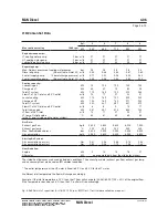
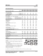
A
min. 4,74 4,774 5,374 5,974 6,574
A
vailable on r
equest
Fore end: A minimum shows basic engine
A maximum shows engine with
built-on tuning wheel
For PTO: See corresponding space
requirement
max. 4,423 5,023 5,623 6,223 6,823
B
2,00
MAN Diesel TCR The required space to the
engine room casing includes
top bracing
ABB TPL
Mitsubishi MET
C
2,638 2,738 2,888 3,038 3,038
MAN Diesel TCR Dimension according to tur-
bocharger choice at nominal
MCR
2,377 2,578 2,728 2,878 2,878
ABB TPL
2,343 2,525 2,675 2,825 2,825
Mitsubishi MET
D
,923 ,963 2,003 2,038 2,073
The dimension includes a cofferdam of 600 mm
and must fulfil minimum height to tank top ac-
cording to classification rules
E
5,25
(same height for electrical and man-
ual crane)
The minimum distance from crankshaft centre
line to lower edge of deck beam, when using
MAN B&W Double Jib Crane
F
5,400
Minimum overhaul height, normal lifting
procedure
5,350
Minimum overhaul height, reduced height lifting
procedure
G
,900
See ‘Engine Top Bracing’, if top bracing fitted
on camshaft side
H
4,67 4,67 4,67 4,67 4,67
MAN Diesel TCR Dimension according to tur-
bocharger choice at nominal
MCR
-
-
-
-
-
ABB TPL
3,860 3,860 3,860 3,860 3,860
Mitsubishi MET
I
,340 ,340 ,340 ,340 ,340
MAN Diesel TCR Dimension according to tur-
bocharger choice at nominal
MCR
-
-
-
-
-
ABB TPL
,070 ,070 ,070 ,80 ,80
Mitsubishi MET
J
360
Space for tightening control of holding down
bolts
K
See text
K must be equal to or larger than the propeller
shaft, if the propeller shaft is to be drawn into
the engine room
L
2,920 2,920 3,380 3,380 3,380
Space for air cooler element overhaul
M
2,230 2,230 2,920 2,920 2,290
Space for water mist catcher overhaul
N
,26
The distances cover required space and
hook travelling width for turbocharger TCR22
O
,466
R
782
S
84
V
0°, 5°, 30°, 45°, 60°, 75°, 90°
Maximum 5° when engine room has minimum
headroom above the turbocharger
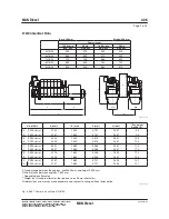
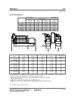
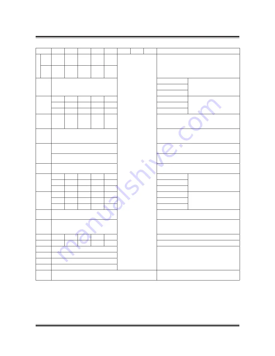
Fig. 5.02.01b: Space requirement for the engine
Summary of Contents for B&W L35MC6-TII
Page 4: ......
Page 10: ......
Page 18: ......
Page 19: ...MAN B W MAN Diesel Engine Design 1 ...
Page 20: ......
Page 35: ...MAN B W MAN Diesel Engine Layout and Load Diagrams SFOC 2 ...
Page 36: ......
Page 52: ......
Page 64: ......
Page 65: ...MAN B W MAN Diesel Turbocharger Selection Exhaust Gas By pass 3 ...
Page 66: ......
Page 72: ......
Page 73: ...MAN B W MAN Diesel Electricity Production 4 ...
Page 74: ......
Page 95: ...MAN B W MAN Diesel Installation Aspects 5 ...
Page 96: ......
Page 132: ......
Page 146: ......
Page 147: ...MAN B W MAN Diesel List of Capacities Pumps Coolers Exhaust Gas 6 ...
Page 148: ......
Page 171: ...MAN B W MAN Diesel Fuel 7 ...
Page 172: ......
Page 186: ......
Page 187: ...MAN B W MAN Diesel Lubricating Oil 8 ...
Page 188: ......
Page 203: ...MAN B W MAN Diesel Cylinder Lubrication 9 ...
Page 204: ......
Page 213: ...MAN B W MAN Diesel Piston Rod Stuffing Box Drain Oil 10 ...
Page 214: ......
Page 215: ......
Page 217: ...MAN B W MAN Diesel Central Cooling Water System 11 ...
Page 218: ......
Page 223: ...MAN B W MAN Diesel Seawater Cooling System 12 ...
Page 224: ......
Page 234: ......
Page 235: ...MAN B W MAN Diesel Starting and Control Air 13 ...
Page 236: ......
Page 242: ......
Page 243: ...MAN B W MAN Diesel Scavenge Air 14 ...
Page 244: ......
Page 256: ......
Page 257: ...MAN B W MAN Diesel Exhaust Gas 15 ...
Page 258: ......
Page 272: ......
Page 273: ...MAN B W MAN Diesel Engine Control System 16 ...
Page 274: ......
Page 289: ...MAN B W MAN Diesel Vibration Aspects 17 ...
Page 290: ......
Page 304: ......
Page 305: ...MAN B W MAN Diesel Monitoring Systems and Instrumentation 18 ...
Page 306: ......
Page 328: ......
Page 329: ...MAN B W MAN Diesel Dispatch Pattern Testing Spares and Tools 19 ...
Page 330: ......
Page 360: ......
Page 361: ...MAN B W MAN Diesel Project Suppport and Documentation 20 ...
Page 362: ......
Page 371: ...MAN B W MAN Diesel Appendix A ...
Page 372: ......


