MAN B&W
6.04
Page 7 of 12
MAN Diesel
198 72 12-9.0
MAN B&W S50MC-C8-TII
Calculation of Freshwater Production for Derated Engine
Example 2:
Freshwater production
from a derated 6S50MC-C8-TII with high efficiency MAN Diesel turbocharger type
TCA and fixed pitch propeller.
Based on the engine ratings below, this example will show how to calculate the expected available jacket
cooling water heat removed from the diesel engine, together with the corresponding freshwater production
from a freshwater generator.
The calculation is made for the service rating (S) of the diesel engine being 80% of the specified MCR.
Nominal MCR, (L
1
)
P
L1
: 9,960 kW (100.0%) and 127.0 r/min (100.0%)
Specified MCR, (M)
P
M
: 8,466 kW (85.0%) and 114.3 r/min (90.0%)
Optmising point, (O) P
O
: 8,466 kW (85.0%) and 114.3 r/min (90.0%), P
O
= 100.0% of P
M
Service rating, (S)
P
S
: 6,773 kW and 106.1 r/min, P
S
= 80.0% of P
M
and P
S
= 80.0% of P
O
Ambient reference conditions: 20 °C air and 18 °C cooling water.
The expected available jacket cooling water heat
at service rating is found as follows:
Q
jw,L1
= 1,450 kW from List of Capacities
Q
jw%
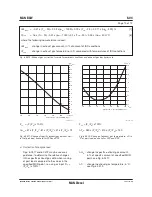
= 88.5% using 85.0% power and 90.0%
speed for O in Fig. 6.04.02
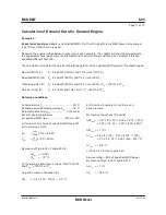
By means of equation [1], and using factor 0.88 for
actual ambient condition the heat dissipation in
the optmising point (O) is found:
Q
jw,O
= Q
jw,L1
x
Q
jw%
___
100
x 0.88
= 1,450 x
88.5
___
100
x 0.88 = 1,129 kW
By means of equation [2], the heat dissipation in
the service point (S) i.e. for 80.0% of optmising
power, is found:
k
p
= 0.852 using 80.0% in Fig. 6.04.04
Q
jw
= Q
jw,O
x k
p
= 1,129 x 0.852 = 962 kW
15%/0%
For the service point the corresponding expected
obtainable freshwater production from a freshwa-
ter generator of the single effect vacuum evapora-
tor type is then found from equation [3]:
M
fw
= 0.03 x Q
jw
= 0.03 x 962 = 28.9 t/24h
15%/0%
Summary of Contents for B&W S50MC-C8-TII
Page 4: ......
Page 10: ......
Page 18: ......
Page 19: ...MAN B W MAN Diesel Engine Design 1 ...
Page 20: ......
Page 35: ...MAN B W MAN Diesel Engine Layout and Load Diagrams SFOC 2 ...
Page 36: ......
Page 52: ......
Page 64: ......
Page 65: ...MAN B W MAN Diesel Turbocharger Selection Exhaust Gas By pass 3 ...
Page 66: ......
Page 72: ......
Page 73: ...MAN B W MAN Diesel Electricity Production 4 ...
Page 74: ......
Page 106: ......
Page 107: ...MAN B W MAN Diesel Installation Aspects 5 ...
Page 108: ......
Page 146: ......
Page 170: ......
Page 171: ...MAN B W MAN Diesel List of Capacities Pumps Coolers Exhaust Gas 6 ...
Page 172: ......
Page 192: ......
Page 193: ...MAN B W MAN Diesel Fuel 7 ...
Page 194: ......
Page 208: ......
Page 209: ...MAN B W MAN Diesel Lubricating Oil 8 ...
Page 210: ......
Page 223: ...MAN B W MAN Diesel Cylinder Lubrication 9 ...
Page 224: ......
Page 233: ...MAN B W MAN Diesel Piston Rod Stuffing Box Drain Oil 10 ...
Page 234: ......
Page 236: ......
Page 237: ...MAN B W MAN Diesel Central Cooling Water System 11 ...
Page 238: ......
Page 243: ...MAN B W MAN Diesel Seawater Cooling System 12 ...
Page 244: ......
Page 254: ......
Page 255: ...MAN B W MAN Diesel Starting and Control Air 13 ...
Page 256: ......
Page 262: ......
Page 263: ...MAN B W MAN Diesel Scavenge Air 14 ...
Page 264: ......
Page 276: ......
Page 277: ...MAN B W MAN Diesel Exhaust Gas 15 ...
Page 278: ......
Page 292: ......
Page 293: ...MAN B W MAN Diesel Engine Control System 16 ...
Page 294: ......
Page 309: ...MAN B W MAN Diesel Vibration Aspects 17 ...
Page 310: ......
Page 324: ......
Page 325: ...MAN B W MAN Diesel Monitoring Systems and Instrumentation 18 ...
Page 326: ......
Page 348: ......
Page 349: ...MAN B W MAN Diesel Dispatch Pattern Testing Spares and Tools 19 ...
Page 350: ......
Page 388: ......
Page 389: ...MAN B W MAN Diesel Project Suppport and Documentation 20 ...
Page 390: ......
Page 399: ...MAN B W MAN Diesel Appendix A ...
Page 400: ......


