MAN B&W
7.04
Page of
MAN Diesel
198 67 69-6.0
MAN B&W S50MC-C7/8, S50ME-C7/8, S46MC-C7/8
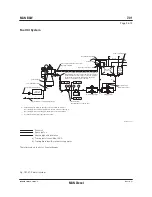
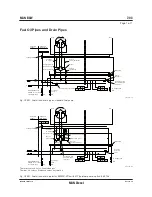
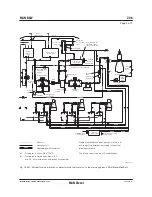
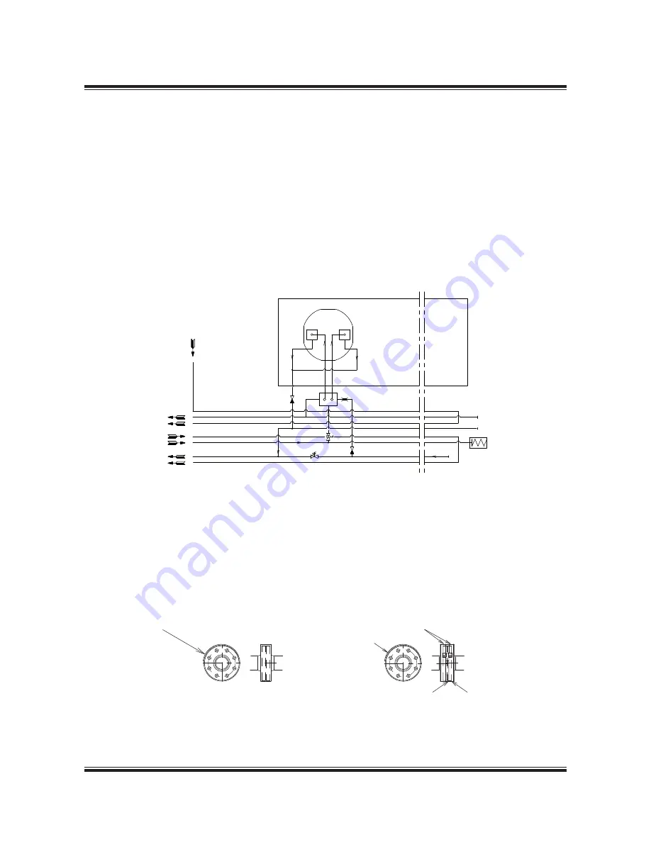
Fuel Oil Pipe Heat Tracing
183 15 33-1.2.0a
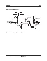
Fig. 7.04.03: Fuel oil pipe heat tracing
The letters refer to list of ‘Counterflanges’
!FT
&ORE
"8
!&
8
&
"&
"$
&ROMæFRESHæCOOLING
WATERæOUTLET
The steam tracing of the fuel oil pipes is intended
to operate in two situations:
1. When the circulation pump is running, there
will be a temperature loss in the piping, see
Fig. 7.04.02. This loss is very small, therefore
tracing in this situation is only necessary with
very long fuel supply lines.
2. When the circulation pump is stopped with
heavy fuel oil in the piping and the pipes have
cooled down to engine room temperature, as
it is not possible to pump the heavy fuel oil.
In this situation the fuel oil must be heated to
pumping temperature of about 50 ºC.
To heat the pipe to pumping level we recom-
mend to use 100 watt leaking/meter pipe.
178 52 555.2
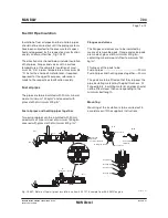
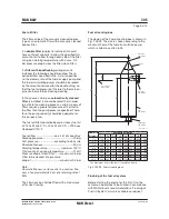
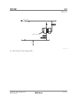
Fig. 7.04.04b: Spray Shields by clamping bands
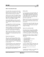
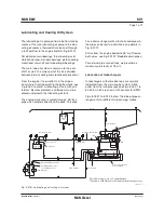
In order to fulfil IMO regulations, fuel oil and lubri-
cating oil pipe assemblies are to be enclosed by
spray shields as shown in Fig. 7.04.04a and b.
!NTIçSPLASHINGæTAPE
#LAMPINGæBANDS
0LATEææMMæTHICKNESS
4HEæTAPEæISæTOæBEæWRAPPEDæINæACCORDANCEæWITHæ
THEæMAKERSæINSTRUCTIONæFORæCLASSæAPPROVAL
4HEæWIDTHæISæTOæCOVERæ
HEADæOFæBOLTSæANDæNUTS
/VERLAP
Fig. 7.04.04a: Spray Shields by anti-splashing tape
To avoid leaks, the spray shields are to be in-
stalled after pressure testing of the pipe system.
Fuel Oil and Lubricating Oil Pipe Spray Shields
Summary of Contents for B&W S50MC-C8-TII
Page 4: ......
Page 10: ......
Page 18: ......
Page 19: ...MAN B W MAN Diesel Engine Design 1 ...
Page 20: ......
Page 35: ...MAN B W MAN Diesel Engine Layout and Load Diagrams SFOC 2 ...
Page 36: ......
Page 52: ......
Page 64: ......
Page 65: ...MAN B W MAN Diesel Turbocharger Selection Exhaust Gas By pass 3 ...
Page 66: ......
Page 72: ......
Page 73: ...MAN B W MAN Diesel Electricity Production 4 ...
Page 74: ......
Page 106: ......
Page 107: ...MAN B W MAN Diesel Installation Aspects 5 ...
Page 108: ......
Page 146: ......
Page 170: ......
Page 171: ...MAN B W MAN Diesel List of Capacities Pumps Coolers Exhaust Gas 6 ...
Page 172: ......
Page 192: ......
Page 193: ...MAN B W MAN Diesel Fuel 7 ...
Page 194: ......
Page 208: ......
Page 209: ...MAN B W MAN Diesel Lubricating Oil 8 ...
Page 210: ......
Page 223: ...MAN B W MAN Diesel Cylinder Lubrication 9 ...
Page 224: ......
Page 233: ...MAN B W MAN Diesel Piston Rod Stuffing Box Drain Oil 10 ...
Page 234: ......
Page 236: ......
Page 237: ...MAN B W MAN Diesel Central Cooling Water System 11 ...
Page 238: ......
Page 243: ...MAN B W MAN Diesel Seawater Cooling System 12 ...
Page 244: ......
Page 254: ......
Page 255: ...MAN B W MAN Diesel Starting and Control Air 13 ...
Page 256: ......
Page 262: ......
Page 263: ...MAN B W MAN Diesel Scavenge Air 14 ...
Page 264: ......
Page 276: ......
Page 277: ...MAN B W MAN Diesel Exhaust Gas 15 ...
Page 278: ......
Page 292: ......
Page 293: ...MAN B W MAN Diesel Engine Control System 16 ...
Page 294: ......
Page 309: ...MAN B W MAN Diesel Vibration Aspects 17 ...
Page 310: ......
Page 324: ......
Page 325: ...MAN B W MAN Diesel Monitoring Systems and Instrumentation 18 ...
Page 326: ......
Page 348: ......
Page 349: ...MAN B W MAN Diesel Dispatch Pattern Testing Spares and Tools 19 ...
Page 350: ......
Page 388: ......
Page 389: ...MAN B W MAN Diesel Project Suppport and Documentation 20 ...
Page 390: ......
Page 399: ...MAN B W MAN Diesel Appendix A ...
Page 400: ......


