MAN B&W
11.02
Page 1 of 1
MAN Diesel
MAN B&W MC/MCC, ME/MEC/MEGI/ME-B engines
198 40 579.5
Central Cooling Water System
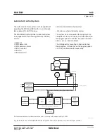
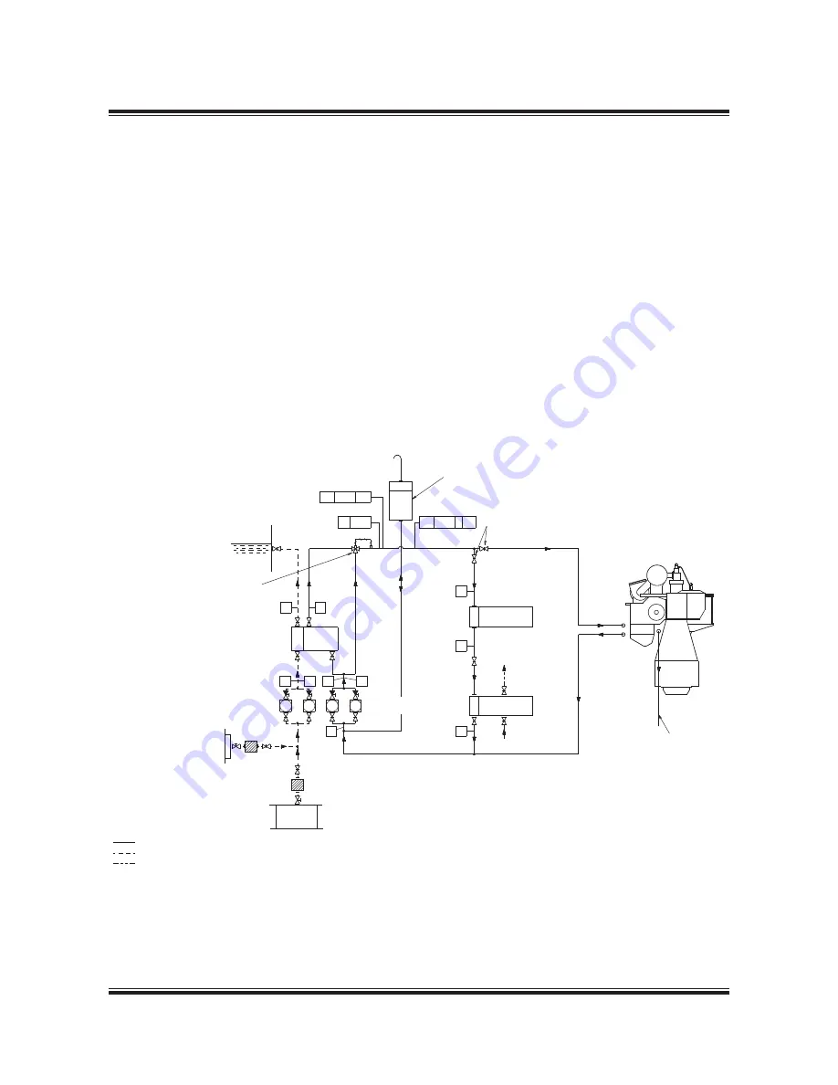
Fig. 11.02.01: Central cooling water system
The central cooling water system is characterised
by having only one heat exchanger cooled by
seawater, and by the other coolers, including the
jacket water cooler, being cooled by central cool-
ing water.
In order to prevent too high a scavenge air tem-
perature, the cooling water design temperature
in the central cooling water system is normally 36
°C, corresponding to a maximum seawater tem-
perature of 32 °C.
Our recommendation of keeping the cooling water
inlet temperature to the main engine scavenge
air cooler as low as possible also applies to the
central cooling system. This means that the tem-
perature control valve in the central cooling water
circuit is to be set to minimum 10 °C, whereby the
temperature follows the outboard seawater tem-
perature when central cooling water temperature
exceeds 10 °C.
For external pipe connections, we prescribe the
following maximum water velocities:
Jacket water ................................................ 3.0 m/s
Central cooling water .................................. 3.0 m/s
Seawater ..................................................... 3.0 m/s
178 52 771.1
TI
TI
TI
TI
TI
TI
PI
PI
PI
TI
Seawater
outlet
Central
cooler
Seawater
pumps
Central cooling
water pumps
Expansion tank
central cooling water
These valves to be provided
with graduated scale
Lubricating
oil cooler
Jacket water
cooler
N
P
AS
Main
engine
Cooling water
drain air cooler
Regarding the lubricating oil coolers,
this valve should be adjusted so that
the inlet temperature of the cooling
water is not below 10 °C
Air pockets, if any, in the pipe line
between the pumps, must be vented
to the expansion tank
Seawater
inlet
Seawater
inlet
Jacket cooling water
Sea water
Fuel oil
The letters refer to list of ‘Counterflanges’, Fig. 5.10.01
PT 8421 AL
TE 8431 I AL
TI 8431
The item No. refer to ‘Guidance values automation’
Summary of Contents for B&W S50MC-C8-TII
Page 4: ......
Page 10: ......
Page 18: ......
Page 19: ...MAN B W MAN Diesel Engine Design 1 ...
Page 20: ......
Page 35: ...MAN B W MAN Diesel Engine Layout and Load Diagrams SFOC 2 ...
Page 36: ......
Page 52: ......
Page 64: ......
Page 65: ...MAN B W MAN Diesel Turbocharger Selection Exhaust Gas By pass 3 ...
Page 66: ......
Page 72: ......
Page 73: ...MAN B W MAN Diesel Electricity Production 4 ...
Page 74: ......
Page 106: ......
Page 107: ...MAN B W MAN Diesel Installation Aspects 5 ...
Page 108: ......
Page 146: ......
Page 170: ......
Page 171: ...MAN B W MAN Diesel List of Capacities Pumps Coolers Exhaust Gas 6 ...
Page 172: ......
Page 192: ......
Page 193: ...MAN B W MAN Diesel Fuel 7 ...
Page 194: ......
Page 208: ......
Page 209: ...MAN B W MAN Diesel Lubricating Oil 8 ...
Page 210: ......
Page 223: ...MAN B W MAN Diesel Cylinder Lubrication 9 ...
Page 224: ......
Page 233: ...MAN B W MAN Diesel Piston Rod Stuffing Box Drain Oil 10 ...
Page 234: ......
Page 236: ......
Page 237: ...MAN B W MAN Diesel Central Cooling Water System 11 ...
Page 238: ......
Page 243: ...MAN B W MAN Diesel Seawater Cooling System 12 ...
Page 244: ......
Page 254: ......
Page 255: ...MAN B W MAN Diesel Starting and Control Air 13 ...
Page 256: ......
Page 262: ......
Page 263: ...MAN B W MAN Diesel Scavenge Air 14 ...
Page 264: ......
Page 276: ......
Page 277: ...MAN B W MAN Diesel Exhaust Gas 15 ...
Page 278: ......
Page 292: ......
Page 293: ...MAN B W MAN Diesel Engine Control System 16 ...
Page 294: ......
Page 309: ...MAN B W MAN Diesel Vibration Aspects 17 ...
Page 310: ......
Page 324: ......
Page 325: ...MAN B W MAN Diesel Monitoring Systems and Instrumentation 18 ...
Page 326: ......
Page 348: ......
Page 349: ...MAN B W MAN Diesel Dispatch Pattern Testing Spares and Tools 19 ...
Page 350: ......
Page 388: ......
Page 389: ...MAN B W MAN Diesel Project Suppport and Documentation 20 ...
Page 390: ......
Page 399: ...MAN B W MAN Diesel Appendix A ...
Page 400: ......

