MAN B&W
17.01
Page 1 of 1
MAN Diesel
198 41 405.3
MAN B&W MC/MCC, ME/MEC/MEGI/ME-B engines
Vibration Aspects
The vibration characteristics of the twostroke low
speed diesel engines can for practical purposes
be split up into four categories, and if the adequate
countermeasures are considered from the early
project stage, the influence of the excitation sour
ces can be minimised or fully compensated.
In general, the marine diesel engine may influence
the hull with the following:
• External unbalanced moments
These can be classified as unbalanced 1st and
2nd order external moments, which need to be
considered only for certain cylinder numbers
• Guide force moments
• Axial vibrations in the shaft system
• Torsional vibrations in the shaft system.
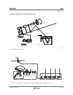
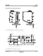
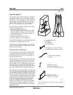
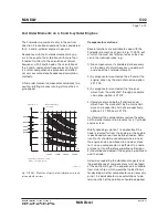
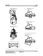
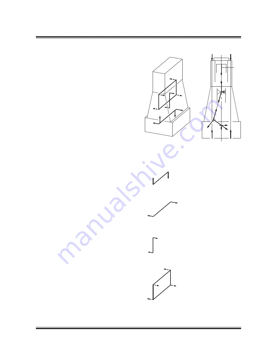
The external unbalanced moments and guide force
moments are illustrated in Fig. 17.01.01.
In the following, a brief description is given of their
origin and of the proper countermeasures needed
to render them harmless.
External unbalanced moments
The inertia forces originating from the unbalanced
rotating and reciprocating masses of the engine
create unbalanced external moments although the
external forces are zero.
Of these moments, the 1st order (one cycle per revo
lution) and the 2nd order (two cycles per revolution)
need to be considered for engines with a low num
ber of cylinders. On 7cylinder engines, also the 4th
order external moment may have to be examined.
The inertia forces on engines with more than 6 cylin
ders tend, more or less, to neutralise themselves.
Countermeasures have to be taken if hull resonance
occurs in the operating speed range, and if the vibra
tion level leads to higher accelerations and/or velo ci
ties than the guidance values given by international
standards or recommendations (for instance related
to special agreement between shipowner and ship
yard). The natural frequency of the hull depends
on the hull’s rigidity and distribution of masses,
whereas the vibration level at resonance depends
mainly on the magnitude of the external moment
and the engine’s position in relation to the vibration
nodes of the ship.
C
C
A
B
D
A – Combustion pressure
B – Guide force
C – Staybolt force
D – Main bearing force
1st order moment vertical 1 cycle/rev.
2nd order moment, vertical 2 cycle/rev.
1st order moment, horizontal
1 cycle/rev.
Guide force moment,
H transverse Z cycles/rev.
Z is 1 or 2 times number of cylinder
Fig. 17.01.01: External unbalanced moments and guide
force moments
Guide force moment,
X transverse Z cycles/rev.
Z = 1, 2, 3 ... 11, 12, 14
178 06 828.2
Summary of Contents for B&W S50MC-C8-TII
Page 4: ......
Page 10: ......
Page 18: ......
Page 19: ...MAN B W MAN Diesel Engine Design 1 ...
Page 20: ......
Page 35: ...MAN B W MAN Diesel Engine Layout and Load Diagrams SFOC 2 ...
Page 36: ......
Page 52: ......
Page 64: ......
Page 65: ...MAN B W MAN Diesel Turbocharger Selection Exhaust Gas By pass 3 ...
Page 66: ......
Page 72: ......
Page 73: ...MAN B W MAN Diesel Electricity Production 4 ...
Page 74: ......
Page 106: ......
Page 107: ...MAN B W MAN Diesel Installation Aspects 5 ...
Page 108: ......
Page 146: ......
Page 170: ......
Page 171: ...MAN B W MAN Diesel List of Capacities Pumps Coolers Exhaust Gas 6 ...
Page 172: ......
Page 192: ......
Page 193: ...MAN B W MAN Diesel Fuel 7 ...
Page 194: ......
Page 208: ......
Page 209: ...MAN B W MAN Diesel Lubricating Oil 8 ...
Page 210: ......
Page 223: ...MAN B W MAN Diesel Cylinder Lubrication 9 ...
Page 224: ......
Page 233: ...MAN B W MAN Diesel Piston Rod Stuffing Box Drain Oil 10 ...
Page 234: ......
Page 236: ......
Page 237: ...MAN B W MAN Diesel Central Cooling Water System 11 ...
Page 238: ......
Page 243: ...MAN B W MAN Diesel Seawater Cooling System 12 ...
Page 244: ......
Page 254: ......
Page 255: ...MAN B W MAN Diesel Starting and Control Air 13 ...
Page 256: ......
Page 262: ......
Page 263: ...MAN B W MAN Diesel Scavenge Air 14 ...
Page 264: ......
Page 276: ......
Page 277: ...MAN B W MAN Diesel Exhaust Gas 15 ...
Page 278: ......
Page 292: ......
Page 293: ...MAN B W MAN Diesel Engine Control System 16 ...
Page 294: ......
Page 309: ...MAN B W MAN Diesel Vibration Aspects 17 ...
Page 310: ......
Page 324: ......
Page 325: ...MAN B W MAN Diesel Monitoring Systems and Instrumentation 18 ...
Page 326: ......
Page 348: ......
Page 349: ...MAN B W MAN Diesel Dispatch Pattern Testing Spares and Tools 19 ...
Page 350: ......
Page 388: ......
Page 389: ...MAN B W MAN Diesel Project Suppport and Documentation 20 ...
Page 390: ......
Page 399: ...MAN B W MAN Diesel Appendix A ...
Page 400: ......


