MAN B&W MC/MCC, ME/MEC/MEGI/ME-B engines
198 46 725.8
MAN B&W
5.13
Page 2 of 2
MAN Diesel
MAN Diesel
The mechanical top bracing is to be made by the
shipyard in accordance with MAN Diesel & Turbo
instructions.
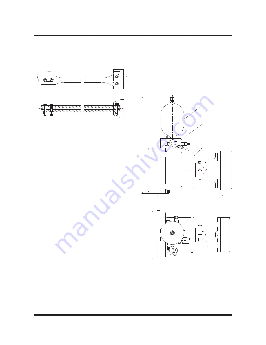
178 23 61-6.1
Fig. 5.13.01: Mechanical top bracing stiffener.
Option: 4 83 112
Hydraulic top bracing
The hydraulic top bracing is an alternative to the
mechanical top bracing used mainly on engines
with a cylinder bore of 50 or more. The installation
normally features two, four or six independently
working top bracing units.
The top bracing unit consists of a single-acting hy-
draulic cylinder with a hydraulic control unit and an
accumulator mounted directly on the cylinder unit.
The top bracing is controlled by an automatic
switch in a control panel, which activates the top
bracing when the engine is running. It is possi-
ble to programme the switch to choose a certain
rpm range, at which the top bracing is active. For
service purposes, manual control from the control
panel is also possible.
When active, the hydraulic cylinder provides a
pressure on the engine in proportion to the vibra-
tion level. When the distance between the hull and
engine increases, oil flows into the cylinder under
pressure from the accumulator. When the dis-
tance decreases, a non-return valve prevents the
oil from flowing back to the accumulator, and the
pressure rises. If the pressure reaches a preset
maximum value, a relief valve allows the oil to flow
back to the accumulator, hereby maintaining the
force on the engine below the specified value.
By a different pre-setting of the relief valve, the
top bracing is delivered in a low-pressure version
(26 bar) or a high-pressure version (40 bar).
The top bracing unit is designed to allow dis-
placements between the hull and engine caused
by thermal expansion of the engine or different
loading conditions of the vessel.
178 57 48-8.0
Fig. 5.13.02: Outline of a hydraulic top bracing unit.
The unit is installed with the oil accumulator pointing
either up or down. Option: 4 83 123
AA
A
A
Hydraulic Control Unit
Oil Accumulator
Cylinder Unit
25
0
14
350
684
320
28
0
475
Engine side
Hull side
Summary of Contents for B&W S50ME-B9.3-TII
Page 4: ......
Page 10: ......
Page 11: ...MAN B W MAN Diesel Engine Design 1 ...
Page 12: ......
Page 27: ...MAN B W MAN Diesel Engine Layout and Load Diagrams SFOC 2 ...
Page 28: ......
Page 53: ...MAN B W MAN Diesel Turbocharger Selection Exhaust Gas By pass 3 ...
Page 54: ......
Page 58: ......
Page 59: ...MAN B W MAN Diesel Electricity Production 4 ...
Page 60: ......
Page 92: ......
Page 93: ...MAN B W MAN Diesel Installation Aspects 5 ...
Page 94: ......
Page 124: ......
Page 133: ...MAN B W MAN Diesel List of Capacities Pumps Coolers Exhaust Gas 6 ...
Page 134: ......
Page 154: ......
Page 155: ...MAN B W MAN Diesel Fuel 7 ...
Page 156: ......
Page 170: ......
Page 171: ...MAN B W MAN Diesel Lubricating Oil 8 ...
Page 172: ......
Page 188: ......
Page 189: ...MAN B W MAN Diesel Cylinder Lubrication 9 ...
Page 190: ......
Page 199: ...MAN B W MAN Diesel Piston Rod Stuffing Box Drain Oil 10 ...
Page 200: ......
Page 202: ......
Page 203: ...MAN B W MAN Diesel Central Cooling Water System 11 ...
Page 204: ......
Page 209: ...MAN B W MAN Diesel Seawater Cooling System 12 ...
Page 210: ......
Page 220: ......
Page 221: ...MAN B W MAN Diesel Starting and Control Air 13 ...
Page 222: ......
Page 227: ...MAN B W MAN Diesel Scavenge Air 14 ...
Page 228: ......
Page 239: ...MAN B W MAN Diesel Exhaust Gas 15 ...
Page 240: ......
Page 254: ......
Page 255: ...MAN B W MAN Diesel Engine Control System 16 ...
Page 256: ......
Page 265: ...MAN B W MAN Diesel Vibration Aspects 17 ...
Page 266: ......
Page 280: ......
Page 281: ...MAN B W MAN Diesel Monitoring Systems and Instrumentation 18 ...
Page 282: ......
Page 302: ......
Page 306: ......
Page 307: ...MAN B W MAN Diesel Dispatch Pattern Testing Spares and Tools 19 ...
Page 308: ......
Page 322: ......
Page 323: ...MAN B W MAN Diesel Project Support and Documentation 20 ...
Page 324: ......
Page 332: ......
Page 333: ...MAN B W MAN Diesel Appendix A ...
Page 334: ......


