MAN B&W
6.04
Page 9 of 12
MAN Diesel
S60ME-B8-TII, S50ME-B8/9-TII,
S46MC-C/ME-B8-TII, S42MC7,
S40ME-B9-TII, S35ME-B9-TII,
S35MC7, L35MC6, S26MC6
198 63 69-4.1
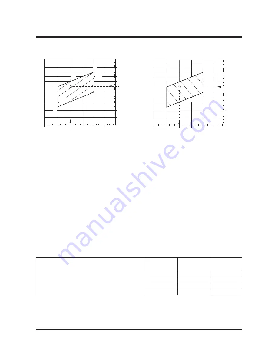
∆
m
M%
: change of specific exhaust gas amount, in
% of specific gas amount at nominal MCR
(L
1
), see Fig. 6.04.07.
∆
T
M
: change in exhaust gas temperature after
turbocharger relative to the L1 value, in °C,
see Fig. 6.04.08. (P
O
= P
M
)
b) Correction for actual ambient conditions and
backpressure
For ambient conditions other than ISO
3046-1:2002 (E) and and backpressure other
than 300 mm WC at specified MCR point (M),
the correction factors stated in the table in
Fig. 6.04.09 may be used as a guide, and the
corresponding relative change in the exhaust
gas data may be found from equations [7] and
[8], shown in Fig. 6.04.10.
Parameter
Change
Change of
exhaust gas
temperature
Change of
exhaust gas
amount
Blower inlet temperature
+ 10° C
+ 16.0° C
4.1 %
Blower inlet pressure (barometric pressure)
+ 10 mbar
0.1° C
+ 0.3 %
Charge air coolant temperature (seawater temperature)
+ 10° C
+ 1.0° C
+ 1.9 %
Exhaust gas back pressure at the specified MCR point
+ 100 mm WC
+ 5.0° C
1.1 %
Fig. 6.04.09: Correction of exhaust gas data for ambient conditions and exhaust gas back pressure
∆
m
M%
= 14 x ln (P
M
/P
L1
) – 24 x ln (n
M
/n
L1
)
Fig. 6.04.07: Change of specific exhaust gas amount,
∆
m
M%
in % of L
1
value
∆
T
M
= 15 x ln (P
M
/P
L1
) + 45 x ln (n
M
/n
L1
)
Fig. 6.04.08: Change of exhaust gas temperature,
∆
T
M
in point M, in °C after turbocharger relative to L
1
value
178 51 11-7.2
178 51 13-0.2
L
4
L
1
L
3
L
2
PM%
M
110%
100%
90%
80%
70%
80%
85%
90%
95%
M%
Specified MCR engine speed, % of L
1
60%
105%
100%
110% n
Specified MCR power, % of L
1
0 °C
∆
T
m
10 °C
8 °C
6 °C
4 °C
12 °C
2 °C
L
2
L
4
L
1
L
3
PM%
110%
100%
90%
80%
70%
80%
85%
90%
95%
M%
Specified MCR engine speed, % of L
1
60%
105%
100%
110% n
∆
m
M%
M
1%
0%
1%
2%
3%
Specified MCR power, % of L
1
Summary of Contents for B&W S50ME-B9.3-TII
Page 4: ......
Page 10: ......
Page 11: ...MAN B W MAN Diesel Engine Design 1 ...
Page 12: ......
Page 27: ...MAN B W MAN Diesel Engine Layout and Load Diagrams SFOC 2 ...
Page 28: ......
Page 53: ...MAN B W MAN Diesel Turbocharger Selection Exhaust Gas By pass 3 ...
Page 54: ......
Page 58: ......
Page 59: ...MAN B W MAN Diesel Electricity Production 4 ...
Page 60: ......
Page 92: ......
Page 93: ...MAN B W MAN Diesel Installation Aspects 5 ...
Page 94: ......
Page 124: ......
Page 133: ...MAN B W MAN Diesel List of Capacities Pumps Coolers Exhaust Gas 6 ...
Page 134: ......
Page 154: ......
Page 155: ...MAN B W MAN Diesel Fuel 7 ...
Page 156: ......
Page 170: ......
Page 171: ...MAN B W MAN Diesel Lubricating Oil 8 ...
Page 172: ......
Page 188: ......
Page 189: ...MAN B W MAN Diesel Cylinder Lubrication 9 ...
Page 190: ......
Page 199: ...MAN B W MAN Diesel Piston Rod Stuffing Box Drain Oil 10 ...
Page 200: ......
Page 202: ......
Page 203: ...MAN B W MAN Diesel Central Cooling Water System 11 ...
Page 204: ......
Page 209: ...MAN B W MAN Diesel Seawater Cooling System 12 ...
Page 210: ......
Page 220: ......
Page 221: ...MAN B W MAN Diesel Starting and Control Air 13 ...
Page 222: ......
Page 227: ...MAN B W MAN Diesel Scavenge Air 14 ...
Page 228: ......
Page 239: ...MAN B W MAN Diesel Exhaust Gas 15 ...
Page 240: ......
Page 254: ......
Page 255: ...MAN B W MAN Diesel Engine Control System 16 ...
Page 256: ......
Page 265: ...MAN B W MAN Diesel Vibration Aspects 17 ...
Page 266: ......
Page 280: ......
Page 281: ...MAN B W MAN Diesel Monitoring Systems and Instrumentation 18 ...
Page 282: ......
Page 302: ......
Page 306: ......
Page 307: ...MAN B W MAN Diesel Dispatch Pattern Testing Spares and Tools 19 ...
Page 308: ......
Page 322: ......
Page 323: ...MAN B W MAN Diesel Project Support and Documentation 20 ...
Page 324: ......
Page 332: ......
Page 333: ...MAN B W MAN Diesel Appendix A ...
Page 334: ......


