MAN B&W
15.04
Page 1 of 2
MAN Diesel
198 40 758.7
MAN B&W MC/MCC, ME/MEC/MEGI/ME-B engines
Components of the Exhaust Gas System
Exhaust gas boiler
Engine plants are usually designed for utilisation of
the heat energy of the exhaust gas for steam pro-
duction or for heating the thermal oil system. The
exhaust gas passes an exhaust gas boiler which is
usually placed near the engine top or in the funnel.
It should be noted that the exhaust gas tempera-
ture and flow rate are influenced by the ambient
conditions, for which reason this should be con-
sidered when the exhaust gas boiler is planned. At
specified MCR, the maximum recommended pres-
sure loss across the exhaust gas boiler is normally
150 mm WC.
This pressure loss depends on the pressure losses
in the rest of the system as mentioned above.
Therefore, if an exhaust gas silencer/spark ar-
rester is not installed, the acceptable pressure loss
across the boiler may be somewhat higher than the
max. of 150 mm WC, whereas, if an exhaust gas
silencer/spark arrester is installed, it may be neces-
sary to reduce the maximum pressure loss.
The above mentioned pressure loss across the
exhaust gas boiler must include the pressure
losses from the inlet and outlet transition pieces.
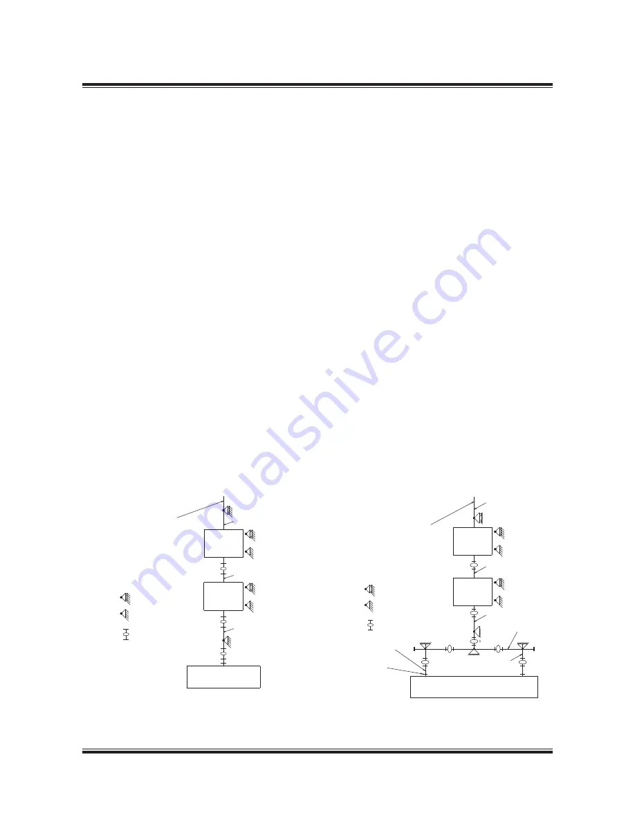
Fig. 15.04.01a: Exhaust gas system, one turbocharger
178 42 783.2
Exhaust gas compensator after turbocharger
When dimensioning the compensator, option:
4 60 610, for the expansion joint on the turbochar-
ger gas outlet transition piece, option: 4 60 601,
the exhaust gas piece and components, are to be
so arranged that the thermal expansions are ab-
sorbed by expansion joints. The heat expansion of
the pipes and the components is to be calculated
based on a temperature increase from 20 °C to
250 °C. The max. expected vertical, transversal
and longitudinal heat expansion of the engine
measured at the top of the exhaust gas transition
piece of the turbocharger outlet are indicated in
Fig. 15.06.01 and Table 15.06.02 as DA, DB and DC.
The movements stated are related to the engine
seating, for DC, however, to the engine centre. The
figures indicate the axial and the lateral movements
related to the orientation of the expansion joints.
The expansion joints are to be chosen with an elas-
ticity that limits the forces and the moments of the
exhaust gas outlet flange of the turbocharger as
stated for each of the turbocharger makers in Table
15.06.04. The orientation of the maximum permis-
sible forces and moments on the gas outlet flange
of the turbocharger is shown in Fig. 15.06.03.
Turbocharger gas
outlet flange
D4
D4
D4
D4
Exhaust gas outlet
to the atmosphere
Slide support
Fixed support
Exhaust gas compensator
Main engine with turbochargers
on exhaust side
Transition piece
Exhaust gas
silencer
Exhaust gas
boiler
D0
Fig. 15.04.01b: Exhaust gas system, two or more TCs
178 33 467.4
Exhaust gas outlet
to the atmosphere
Slide support
Fixed support
Exhaust gas compensator
Main engine with
turbocharger on aft end
D0
D0
D0
Exhaust gas
silencer
Exhaust gas
boiler
Summary of Contents for B&W S50ME-B9.3-TII
Page 4: ......
Page 10: ......
Page 11: ...MAN B W MAN Diesel Engine Design 1 ...
Page 12: ......
Page 27: ...MAN B W MAN Diesel Engine Layout and Load Diagrams SFOC 2 ...
Page 28: ......
Page 53: ...MAN B W MAN Diesel Turbocharger Selection Exhaust Gas By pass 3 ...
Page 54: ......
Page 58: ......
Page 59: ...MAN B W MAN Diesel Electricity Production 4 ...
Page 60: ......
Page 92: ......
Page 93: ...MAN B W MAN Diesel Installation Aspects 5 ...
Page 94: ......
Page 124: ......
Page 133: ...MAN B W MAN Diesel List of Capacities Pumps Coolers Exhaust Gas 6 ...
Page 134: ......
Page 154: ......
Page 155: ...MAN B W MAN Diesel Fuel 7 ...
Page 156: ......
Page 170: ......
Page 171: ...MAN B W MAN Diesel Lubricating Oil 8 ...
Page 172: ......
Page 188: ......
Page 189: ...MAN B W MAN Diesel Cylinder Lubrication 9 ...
Page 190: ......
Page 199: ...MAN B W MAN Diesel Piston Rod Stuffing Box Drain Oil 10 ...
Page 200: ......
Page 202: ......
Page 203: ...MAN B W MAN Diesel Central Cooling Water System 11 ...
Page 204: ......
Page 209: ...MAN B W MAN Diesel Seawater Cooling System 12 ...
Page 210: ......
Page 220: ......
Page 221: ...MAN B W MAN Diesel Starting and Control Air 13 ...
Page 222: ......
Page 227: ...MAN B W MAN Diesel Scavenge Air 14 ...
Page 228: ......
Page 239: ...MAN B W MAN Diesel Exhaust Gas 15 ...
Page 240: ......
Page 254: ......
Page 255: ...MAN B W MAN Diesel Engine Control System 16 ...
Page 256: ......
Page 265: ...MAN B W MAN Diesel Vibration Aspects 17 ...
Page 266: ......
Page 280: ......
Page 281: ...MAN B W MAN Diesel Monitoring Systems and Instrumentation 18 ...
Page 282: ......
Page 302: ......
Page 306: ......
Page 307: ...MAN B W MAN Diesel Dispatch Pattern Testing Spares and Tools 19 ...
Page 308: ......
Page 322: ......
Page 323: ...MAN B W MAN Diesel Project Support and Documentation 20 ...
Page 324: ......
Page 332: ......
Page 333: ...MAN B W MAN Diesel Appendix A ...
Page 334: ......


