MAN B&W
17.02
Page 1 of 3
MAN Diesel
MAN B&W S50MEC, G50ME-B, S50ME-B9,
G45ME-B, S40MC-C, G40ME-B, S40ME-B,
S35MC-C, S35ME-B, S30ME-B
198 68 84-5.4
2nd Order Moments on 4, 5 and 6-cylinder Engines
The 2nd order moment acts only in the vertical
direction. Precautions need only to be considered
for 4, 5 and 6-cylinder engines in general.
Resonance with the 2nd order moment may oc-
cur in the event of hull vibrations with more than
3 nodes. Contrary to the calculation of natural
frequency with 2 and 3 nodes, the calculation of
the 4 and 5-node natural frequencies for the hull
is a rather comprehensive procedure and often
not very accurate, despite advanced calculation
methods.
Compensator solutions
On engines where engine-driven moment com-
pensators cannot be installed aft nor fore, two so-
lutions remain to cope with the 2nd order moment
as shown in Fig. 17.03.02:
1) No compensators, if considered unnecessary
on the basis of natural frequency, nodal point
and size of the 2nd order moment.
2) An electrically driven moment compensator
placed in the steering gear room, as explained
in Section 17.03, option: 4 31 253 or 255.
Briefly speaking, solution 1) is applicable if the
node is located far from the engine, or the engine
is positioned more or less between nodes. Due to
its position in the steering gear room, solution 2)
is not particularly sensitive to the position of the
node.
Determine the need
A decision regarding the vibrational aspects and
the possible use of compensators should prefer-
ably be taken at the contract stage. If no experi-
ence is available from sister ships, which would
be the best basis for deciding whether compensa-
tors are necessary or not, it is advisable to make
calculations to determine this.
If the compensator is initially omitted, measure-
ments taken during the sea trial, or later in service
and with fully loaded ship, will be able to show if a
compensator has to be fitted at all.
Preparation for compensators
If no calculations are available at the contract
stage, we advise to make preparations for the fit-
ting of an electrically driven moment compensator
in the steering compartment, see Section 17.03.
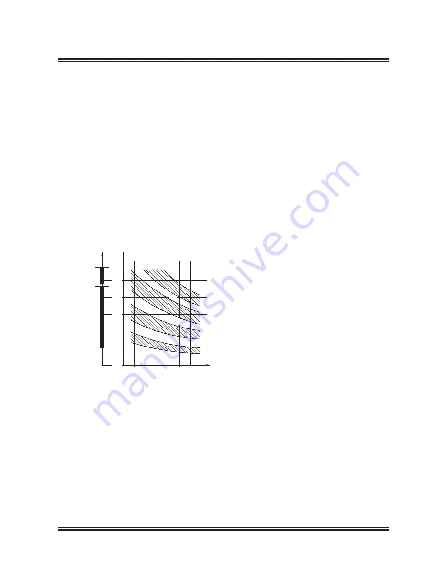
Natural frequency
cycles/min.
4 node
3 node
2 node
20,000
40,000
60,000
dwt
80,000
5 n
ode
Cycles/min. *)
*) Frequency of engine moment
M2V = 2 x engine speed
S50ME-C/ME-B8
150
100
50
200
250
300
S50ME-B9
S40ME-B9
Fig. 17.02.01: Statistics of vertical hull vibrations, an ex-
ample from tankers and bulk carriers
178 61 16-0.1
Summary of Contents for B&W S50ME-B9.3-TII
Page 4: ......
Page 10: ......
Page 11: ...MAN B W MAN Diesel Engine Design 1 ...
Page 12: ......
Page 27: ...MAN B W MAN Diesel Engine Layout and Load Diagrams SFOC 2 ...
Page 28: ......
Page 53: ...MAN B W MAN Diesel Turbocharger Selection Exhaust Gas By pass 3 ...
Page 54: ......
Page 58: ......
Page 59: ...MAN B W MAN Diesel Electricity Production 4 ...
Page 60: ......
Page 92: ......
Page 93: ...MAN B W MAN Diesel Installation Aspects 5 ...
Page 94: ......
Page 124: ......
Page 133: ...MAN B W MAN Diesel List of Capacities Pumps Coolers Exhaust Gas 6 ...
Page 134: ......
Page 154: ......
Page 155: ...MAN B W MAN Diesel Fuel 7 ...
Page 156: ......
Page 170: ......
Page 171: ...MAN B W MAN Diesel Lubricating Oil 8 ...
Page 172: ......
Page 188: ......
Page 189: ...MAN B W MAN Diesel Cylinder Lubrication 9 ...
Page 190: ......
Page 199: ...MAN B W MAN Diesel Piston Rod Stuffing Box Drain Oil 10 ...
Page 200: ......
Page 202: ......
Page 203: ...MAN B W MAN Diesel Central Cooling Water System 11 ...
Page 204: ......
Page 209: ...MAN B W MAN Diesel Seawater Cooling System 12 ...
Page 210: ......
Page 220: ......
Page 221: ...MAN B W MAN Diesel Starting and Control Air 13 ...
Page 222: ......
Page 227: ...MAN B W MAN Diesel Scavenge Air 14 ...
Page 228: ......
Page 239: ...MAN B W MAN Diesel Exhaust Gas 15 ...
Page 240: ......
Page 254: ......
Page 255: ...MAN B W MAN Diesel Engine Control System 16 ...
Page 256: ......
Page 265: ...MAN B W MAN Diesel Vibration Aspects 17 ...
Page 266: ......
Page 280: ......
Page 281: ...MAN B W MAN Diesel Monitoring Systems and Instrumentation 18 ...
Page 282: ......
Page 302: ......
Page 306: ......
Page 307: ...MAN B W MAN Diesel Dispatch Pattern Testing Spares and Tools 19 ...
Page 308: ......
Page 322: ......
Page 323: ...MAN B W MAN Diesel Project Support and Documentation 20 ...
Page 324: ......
Page 332: ......
Page 333: ...MAN B W MAN Diesel Appendix A ...
Page 334: ......


