MAN B&W
4.03
Page 3 of 6
MAN Diesel
198 43 156.3
MAN B&W 98
→
50MC/MC-C/ME/ME-C/ME-B/-GI
Crankshaft gear
lubricated from the main engine lubricating oil system
The figures are to be added to the main engine capacity list:
Nominal output of generator
kW
700
1,200
1,800
2,600
Lubricating oil flow
m
3
/h
4.1
4.1
4.9
6.2
Heat dissipation
kW
12.1
20.8
31.1
45.0
RCF gear
with separate lubricating oil system:
Nominal output of generator
kW
700
1,200
1,800
2,600
Cooling water quantity
m
3
/h
14.1
22.1
30.0
39.0
Heat dissipation
kW
55
92
134
180
El. power for oil pump
kW
11.0
15.0
18.0
21.0
Dosage tank capacity
m
3
0.40
0.51
0.69
0.95
El. power for Renk controller
24V DC ± 10%, 8 amp
From main engine:
Design lube oil pressure: 2.25 bar
Lube oil pressure at crankshaft gear: min. 1 bar
Lube oil working temperature: 50 °C
Lube oil type: SAE 30
Table 4.03.02: Necessary capacities for PTO/RCF, BW III/RCF system
178 33 850.0
Cooling water inlet temperature: 36 °C
Pressure drop across cooler: approximately 0.5 bar
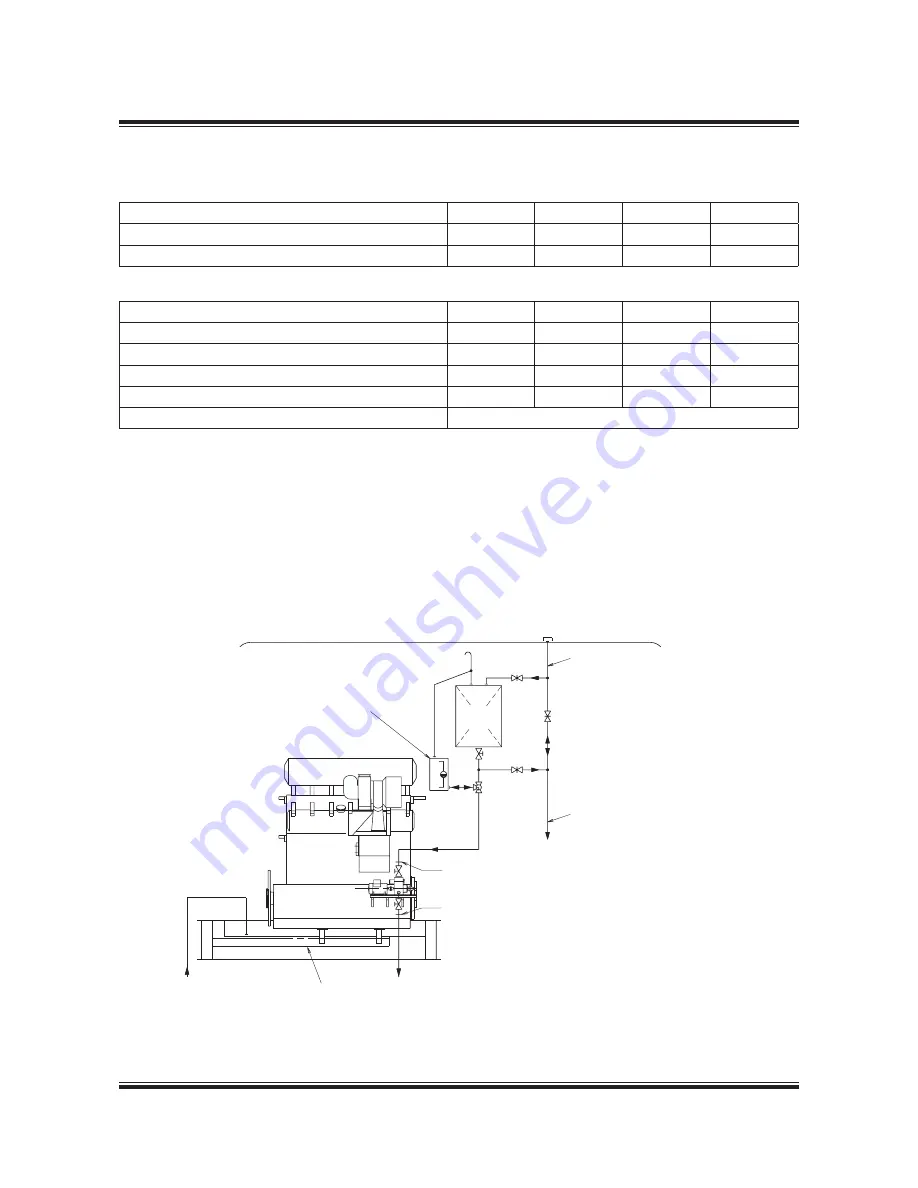
Fill pipe for lube oil system store tank (~ø32)
Drain pipe to lube oil system drain tank (~ø40)
Electric cable between Renk terminal at gearbox
and operator control panel in switchboard: Cable
type FMGCG 19 x 2 x 0.5
The letters refer to the list of ‘Counterflanges’,
which will be extended by the engine builder,
when PTO systems are installed on the main engine
Fig. 4.03.03: Lubricating oil system for RCF gear
178 25 235.0
Filling pipe
Deck
To main engine
DR
Main
engine
Engine
oil
DS
S
S
C/D
To purifier
From purifier
Lube oil
bottom tank
The dimensions
of dosage tank
depend on actual
type of gear
C/D
Summary of Contents for B&W S50ME-B9.3-TII
Page 4: ......
Page 10: ......
Page 11: ...MAN B W MAN Diesel Engine Design 1 ...
Page 12: ......
Page 27: ...MAN B W MAN Diesel Engine Layout and Load Diagrams SFOC 2 ...
Page 28: ......
Page 53: ...MAN B W MAN Diesel Turbocharger Selection Exhaust Gas By pass 3 ...
Page 54: ......
Page 58: ......
Page 59: ...MAN B W MAN Diesel Electricity Production 4 ...
Page 60: ......
Page 92: ......
Page 93: ...MAN B W MAN Diesel Installation Aspects 5 ...
Page 94: ......
Page 124: ......
Page 133: ...MAN B W MAN Diesel List of Capacities Pumps Coolers Exhaust Gas 6 ...
Page 134: ......
Page 154: ......
Page 155: ...MAN B W MAN Diesel Fuel 7 ...
Page 156: ......
Page 170: ......
Page 171: ...MAN B W MAN Diesel Lubricating Oil 8 ...
Page 172: ......
Page 188: ......
Page 189: ...MAN B W MAN Diesel Cylinder Lubrication 9 ...
Page 190: ......
Page 199: ...MAN B W MAN Diesel Piston Rod Stuffing Box Drain Oil 10 ...
Page 200: ......
Page 202: ......
Page 203: ...MAN B W MAN Diesel Central Cooling Water System 11 ...
Page 204: ......
Page 209: ...MAN B W MAN Diesel Seawater Cooling System 12 ...
Page 210: ......
Page 220: ......
Page 221: ...MAN B W MAN Diesel Starting and Control Air 13 ...
Page 222: ......
Page 227: ...MAN B W MAN Diesel Scavenge Air 14 ...
Page 228: ......
Page 239: ...MAN B W MAN Diesel Exhaust Gas 15 ...
Page 240: ......
Page 254: ......
Page 255: ...MAN B W MAN Diesel Engine Control System 16 ...
Page 256: ......
Page 265: ...MAN B W MAN Diesel Vibration Aspects 17 ...
Page 266: ......
Page 280: ......
Page 281: ...MAN B W MAN Diesel Monitoring Systems and Instrumentation 18 ...
Page 282: ......
Page 302: ......
Page 306: ......
Page 307: ...MAN B W MAN Diesel Dispatch Pattern Testing Spares and Tools 19 ...
Page 308: ......
Page 322: ......
Page 323: ...MAN B W MAN Diesel Project Support and Documentation 20 ...
Page 324: ......
Page 332: ......
Page 333: ...MAN B W MAN Diesel Appendix A ...
Page 334: ......


