background image

1

2

3

4

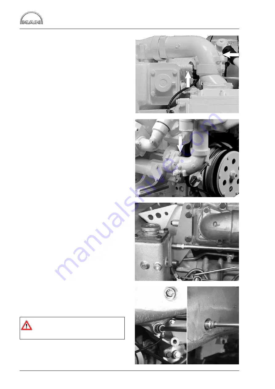
Removing and installing heat exchanger

52

D

Drain off coolant, see page 39

Figs. 1 and 2

Unscrew all pipe connections to the heat ex-
changer.

Fig. 3

Unscrew the mounting bolts at the brackets.

Fig. 4

Unscrew the mounting bolts on the front side of the
engine.

Take off heat exchanger.

Danger:

The heat exchanger is heavy.
Use lifting gear or work with helper.

Summary of Contents for D 2840 LE 301

Page 1: ......

Page 2: ......

Page 3: ...may not always be applicable to the engine in hand which nevertheless does not mean that they are not correct In such cases the repair work is to be planned and carried out in a similar way It is comp...

Page 4: ...parts with different rates of linear expansion under heat e g aluminium and cast iron and leaks may then occur Example The cap of the front crankshaft seal If a sealing agent or an adhesive is used h...

Page 5: ...asked with protective tape again after wards The following pipes are affected Oil supply pipe to turbochargers Fuel pipes between supply pump filter and injection pump Injection pipes protected agains...

Page 6: ...luster for heat exchanger 54 Checking and repairing pipe cluster for heat exchanger 57 Cleaning heat exchanger pipe cluster 59 Disassembling and assembling seawater pump 60 Lubrication Changing oil fi...

Page 7: ...der liners 128 Measuring piston protrusion 132 Attachments Removing and installing starter motor 133 Removing and attaching alternator 134 V belts 136 Removing and installing power take off for hydrau...

Page 8: ...elow using the model type D 2840 LE 301 as an example D The D at the start of the type classification stands for Diesel 28 The numbers 28 indicates that the power plant in question has a bore of 128 m...

Page 9: ...nsure that the engine cannot be ac cidentally started from the bridge by unauthorised persons D The engine must be started and operated only by authorized personnel D When the engine is running do not...

Page 10: ...sible D Never allow the engine to run dry i e without lubricant or coolant Appropriate notices must be attached to engines that are not ready for operation D Today modern components of diesel injectio...

Page 11: ...ecautions to ensure that no oil or Diesel fuel gets into the drains or the ground Caution Risk of contamination of potable water D Filter elements are classed as dangerous waste and must be treated as...

Page 12: ...ective gloves D Clean skin which has been in contact with engine oil Wash thoroughly with soap and water A nailbrush is an effective aid Certain products make it easier to clean your hands Do not use...

Page 13: ...he probable causes and investigate and eliminate these successively on the basis of the table and your own experience This helps to reduce repairs to the required scale and to counteract claims regard...

Page 14: ...loose worn winding defective short to ground x x x x Engine oil viscosity unsuitable not suitable for ambient temperature lubricating oil quality does not correspond to specifications x x Oil level in...

Page 15: ...echanical noise Possible causes x x x x x x x Fuel low pressure system Air in system turn on ignition when bleeding system x x x x x x x x x Fuel low pressure system Fuel pump overflow valve main filt...

Page 16: ...Notes 14...

Page 17: ...relation to the values measured on commissioning the engine D Charging pressure D Exhaust temperature D Coolant and lubricant temperature D Oil pressure and oil consumption D Smoke emissions The foll...

Page 18: ...aining damage and its causes If engines are not pressurised the risk of premature damage to bearing surfaces is very high because it takes a relatively long period of time for the lube oil drawn in fr...

Page 19: ...nkcase or from crankcase bores which may not be plugged can be detected immediately For this purpose mount the engine on an assembly dolly remove the oil pan and install a suitable oil collector under...

Page 20: ...Engine views 18 Engine views D 2842 LE 301 9 10 11 12 9 8 6 5 4 3 2 1 13 14 15 16 17 18 6 7 8...

Page 21: ...r neck Relief valve on coolant surge tank Intercooler Oil filler neck Crankcase breather Air filter Turbocharger Exhaust manifold Starter 11 Oil pan 12 Engine cranking device 13 Alternator 14 Coolant...

Page 22: ...haft High pressure pump lubrication Lubricating oil lines to exhaust turbochargers Oil return line from exhaust turbochargers Holes for main bearing lubrication Oil pump with oil pressure relief valve...

Page 23: ...ng oil lines to exhaust turbochargers Rocker arm lubrication Piston pin lubrication Spray nozzles for piston cooling and cam lubrication Camshaft bearing lubrication Oil intake pipe Oil pressure relie...

Page 24: ...ifold liquid cooled Exhaust pipe liquid cooled Intercooler Coolant temperature measuring point Coolant line with throttle Expansion tank Positive pressure negative pressure valve 11 Coolant filler nec...

Page 25: ...Fuel diagram 23 1 2 4 5 6 1 5 7 8 6 4 5 4 3 2 1 1 7 Injector Tank Injection pump Fuel filter Hand pump with prefilter Fuel pump Valve...

Page 26: ...urpose the speed pickup together with the plate is to be previously detached Fig 3 There is another scale engraved on the flywheel which can be read through an inspection hole in the flywheel housing...

Page 27: ...the specified start of de livery setting see Service Data If not correct start of delivery setting Adjusting start of delivery Fig 7 To adjust the start of delivery the injection pump drive must be ma...

Page 28: ...on pump hub For this two complete turns of the engine are necessary Turn the injection pump camshaft at the drive flange either to the left or right until the markings are aligned with each other Note...

Page 29: ...removal of the injection lines we recommend fitting caps to the connections on the injection nozzles and injection pump This prevents dirt from getting into the injection system Caution Dirt in the i...

Page 30: ...tain fuel Catch emerging fuel in a container Fig 7 Remove timing case cover Note Pipes are attached to the timing case cover To facilitate reassembly note down the positions of the brackets pipe clamp...

Page 31: ...of delivery of individual engines is indicated in the publication Service Data see also page 24 Note In the event of new pumps remove plug from oil supply bore Fig 11 Check whether the injection pump...

Page 32: ...ts on the gear through the inspection hole Two com plete engine turns are necessary for this operation Note Use only M8x22 mounting bolts property class 12 9 Now tighten all mounting bolts to 38 Nm Fi...

Page 33: ...m the injection nozzles and from the injection pump Remove the fuel return lines Fig 3 After removal of the injection lines we recommend fitting caps to the connections on the injection nozzles and in...

Page 34: ...new seal Screw on union nut and tighten to specified torque Tightening torque 120 Nm Fig 7 Example The lubricant which is available as a spray must be applied to the inside of the pressure screw to t...

Page 35: ...e deviation insert a differ ent shim If the pressure is too low insert thicker shims if it is too high insert thinner shims The initial tension of the compression spring de creases if a high number of...

Page 36: ...and petrol or Diesel fuel Clean nozzle needle 2 with a clean cloth Clean coked nozzle needle surface on lathe with a piece of wood not too hard dipped into oil Note To prevent corrosion do not touch l...

Page 37: ...ghtening it to the specified torque see Service Data Check injector on the manual test stand Ensure that the edge type filter is correctly seated in the injector body Fig 9 A dislocated sieve bar filt...

Page 38: ...Clean filter housing and strainer in clean diesel fuel and blow out with compressed air D Reassemble with a new seal D Screw on filter housing and tighten it to 10 12 Nm Fig 4 D Actuate plunger of han...

Page 39: ...Check the filter for leaks Caution Used fuel filters are classed as dangerous waste and must be disposed of accord ingly Change over fuel filter Fig 3 Where the changeover type filter is installed the...

Page 40: ...and 5 An arrow on the filter head indicates the direction of fuel flow D Unscrew bleed screw of first filter in direction of flow by one or two turns D Actuate tappet of hand primer until fuel emer g...

Page 41: ...lations Drain coolant as follows when cooling system has cooled down D Briefly open cap large cap on the filler neck of the expansion tank for pressure compensation D Then take off the cap D Remove dr...

Page 42: ...ed up with coolant either by means of a pump or via the filler neck D The water cooled exhaust manifold and the rear intercooler must be vented during the filling process To this end the exhaust manif...

Page 43: ...en the engine is at operating temperature this can lead to the alarm pressure in the expansion tank when the engine is then put into operation and to a reduction in the engine output Coolant pressure...

Page 44: ...are inserted in the cooling pump housing Check the function of the thermostats as follows D Suspend the thermostat in a bowl of water D Heat up the water D Using a suitable thermometer ascertain the s...

Page 45: ...ts and re move the coolant pump Installing coolant pump and thermo stats Fig 2 Clean the sealing faces on the coolant pump and crankcase with a scraper and fine abrasive paper Stick the new gasket for...

Page 46: ...oolant pump need not be exchanged or repaired because of this trace of permeating coolant For this reason before exchanging or repairing a coolant pump ascertain D whether the cooling circuit shows vi...

Page 47: ...Press D Additional tools to make yourself special tool Fig 1 Mechanical seal Pump bearing Hub Circlip Cap Impeller Pump housing Fig 2 Clamp coolant pump in vice using soft jaws Pull off hub with pull...

Page 48: ...the coolant pump shaft with bearing out of the housing Shaft and bearing are encapsulated and replaced as a single unit only Take off axial face seal Reassembling coolant pump Fig 6 Press in coolant...

Page 49: ...Observe installation note for seal on page 49 Note The seal can be exchanged even without removing the coolant pump shaft Figs 10 and 11 Press impeller slowly on to bearing shaft to ensure correct ga...

Page 50: ...12 13 Repairing coolant pump 48 Figs 12 and 13 Place on the new pump cover and use a suitable pressing die to press the cover into the housing Fit coolant pump with new seal see page 43...

Page 51: ...ing is in perfect condition If the bore shows even the slightest scoring or other minor damage a sealing bead of Dirko Transparent must be applied to collar Fit the seal with a plastic transportation...

Page 52: ...shed immedi ately during the cleaning operation c Fill coolant circuit with a mixture of hot water min 50 C and Henkel P 3 neutrasel 5265 detergent 1 5 by volume 5266 5225 Kluthe Hakopur 316 refer to...

Page 53: ...h a mixture of potable tap water and anti freeze with at least 40 by volume refer to Publication Fuels Lubricants Filler caps and service valves of cooling system The rubber seals on the filler caps a...

Page 54: ...39 Figs 1 and 2 Unscrew all pipe connections to the heat ex changer Fig 3 Unscrew the mounting bolts at the brackets Fig 4 Unscrew the mounting bolts on the front side of the engine Take off heat exc...

Page 55: ...alling heat exchanger 53 Fig 5 Install the heat exchanger in reverse order Tighten the mounting bolts with the prescribed torque Fit pipe connections with new O rings Check the system for leaks Fill c...

Page 56: ...over and the heat exchanger housing arrow Match mark the position of the pipe cluster relative to the heat exchanger housing Fig 2 Remove both covers Remove the O rings Fig 3 Remove the two screw plug...

Page 57: ...hanger 55 Fig 5 Carefully knock pipe cluster out from the other end with a block of wood Caution The pipe cluster is bolted to the heat ex changer See Figs 3 and 4 Figs 6 and 7 Pull out pipe cluster C...

Page 58: ...hanger Figs 8 and 9 The pipe cluster is installed in reverse order When installing the pipe cluster use new O rings total of 4 rings Fig 10 Push pipe cluster into heat exchanger housing Fig 11 Screw i...

Page 59: ...temperature Fig 2 Measure the position of the deflectors Use the pipe cluster side with the collar arrow as refer ence edge this side can be recognised as that end of the pipe cluster with the larger...

Page 60: ...brass brush emery cloth in the area where the soldering is to be effected The area must also be free of grease To effect the soldering use soldering tin DIN 1707 L SN 50 PB SB MAN no 09 43007 0092 mel...

Page 61: ...made of synthetic material such as PE PP PVC GRP etc D Fill container with undiluted genuine pickling liquid at room temperature Lithsolvents ure or engine pick ling fluid RB 06 until the pipe cluster...

Page 62: ...justing washer11 Press shaft with bearing out of the housing Press axial face seal out of the bearing housing Assembling seawater pump Insert new axial face seal in the bearing housing Heat bearing up...

Page 63: ...re filled with hot oil Risk of burns and scalds Fig 2 Remove mounting bolt of the relevant filter bowl Remove filter cup and clean inside Fig 3 Insert a new filter cartridge and fit the filter cup wit...

Page 64: ...cooler housing cover or go over the cover and obstruct removal are to be unscrewed Fig 3 10 cylinder engine Remove oil cooler housing cover with fitted oil coo ler WAF 13 The 5 marked screws hold the...

Page 65: ...bead of Loctite 5900 sealing com pound to the seal Fig 8 Tighten the mounting bolts with the prescribed torque D Screw on oil cooler housing cover with fitted oil cooler Initial torque 50 Nm Angle ti...

Page 66: ...ion of environmental damage Remove oil pan Fig 2 Caution Oil pans are awkward to handle and heavy They may contain residual amounts of en gine oil Use lifting gear or work with a helper Remove the mou...

Page 67: ...ump Fig 6 Fit the oil pump in a vice use protective jaws Remove oil pump cover Pull the driven oil pump wheel from the casing Check the toothed wheels and pump casing for wear see Service Data Fig 7 R...

Page 68: ...f the needle deflection on the dial gauge Installing oil pump Fig 10 Tighten the securing bolts with the prescribed tor que D Before installing check whether the oil pump run smoothly and then fit it...

Page 69: ...ion of environmental damage Remove oil pan Fig 2 Caution Oil pans are awkward to handle and heavy They may contain residual amounts of en gine oil Use lifting gear or work with a helper Remove the mou...

Page 70: ...the toothed wheels and pump casing for wear see Service Data Fig 7 Remove oil pump drive gear To do this lay pump on suitable support and press off drive gear using a mandrel To install it put drive...

Page 71: ...Fig 10 Tighten the securing bolts with the prescribed torque D Before installing check whether the oil pump run smoothly and then fit it them free of ten sion D Screw on pressure relief valve without...

Page 72: ...let it run for a few minutes at low speed Caution If no oil pressure builds up after approx 10 seconds switch off the engine immediately Check oil pressure and check that there is no oil leakage Then...

Page 73: ...il injection nozzle valve Fig 2 Unscrew the oil injection nozzle valve from the body of the oil injection nozzle The valve plunger must move up and down easily If the valve plunger sticks or jams repl...

Page 74: ...hole of the cooling duct in the piston crown and cams without hindrance Bent oil injection nozzles must on no account be repaired Turn the engine The crankshaft drive or pistons must not collide with...

Page 75: ...special tool that is to be fitted to the inspection hole in the flywheel housing Unscrew the start of delivery indicator Fig 2 Unscrew the barring gear Mark the positions of the parts in relation to...

Page 76: ...oosen the mounting bolts of the cover Fig 6 Remove the cover Only replace the front crankshaft gasket as a com plete unit i e replace the bearing race and the radial shaft sealing ring Replacing the b...

Page 77: ...ing race as far as it will go into the press in sleeve on the adapter with collar nut and thrust washer and in Fig 9 Note The bearing race can also be mounted when the cover is fitted Replacing the ra...

Page 78: ...rela tive to the crankshaft is correct Tighten the mounting bolts Tightening torque 260 Nm Fit cranking device Fit and tension V belts see page 138 Figs 15 and 16 Fit and adjust the start of delivery...

Page 79: ...fting gear Fitting the flywheel Fig 3 Insert the guide pins Coat the sealing face on the inside of the flywheel with Antipor 46 sealing compound Place guide mandrels on the flywheel in doing so pay at...

Page 80: ...ured on the contact surface of the starter motor toothed wheel prior to shrinking on the starter motor toothed wheel If the required value is exceeded replace the flywheel Engage the flywheel at the h...

Page 81: ...screwdriver Fig 2 Special tool for levering out the crankshaft seal Fit shaft sealing ring Fig 3 When fitting a new shaft sealing ring you must also replace the flywheel bearing race Insert the new sh...

Page 82: ...bearing race to be exchanged using a puller special tool Fig 2 Insert the new bearing race in the drift special tool in such a way that the inner bevelled side faces the flywheel when fitted later Ca...

Page 83: ...lest damage causes leaks The sealing lip and the bearing race of the flywheel must not be coated with oil or other lubricants On fitting the new sealing ring always replace the bearing race alongside...

Page 84: ...n bodies from entering the engine Removing intake pipe Fig 1 Release the mounting bolts Remove the intake pipe Installing intake pipe Fig 2 Place intake pipe with new seals in position Screw in mounti...

Page 85: ...hand exhaust pipe the oil fil ter bowls must be removed see page 61 Close up oil filter console to prevent dirt or foreign matter from getting into the lube oil circuit Fig 2 Release the mounting bol...

Page 86: ...emoving and installing exhaust pipe 84 Fig 5 Tighten the securing bolts with the prescribed tor que Tightening torque 50 Nm Fig 6 Bolt on the exhaust manifold in diagonal sequence Tightening torque 18...

Page 87: ...ts in relatively early mechanical damage If engine power output is unsatisfactory Ensure correct adjustment of valve clearance speed adjustment to full load stop Also check the following the compressi...

Page 88: ...ssibly steep inclines The crankcase pressure is to high This may be caused by a defective oil separator valve crankcase breather or piston ring wear Compressor coking This can occur when the charge ai...

Page 89: ...Removing turbocharger D Drain off coolant see Page 39 Fig 1 Remove the venting line and intake neck Fig 2 Remove the coolant lines Fig 3 Unscrew the oil supply line and oil return line Fig 4 Remove d...

Page 90: ...order On assembly new seals and new self locking nuts are to be used Tightening torque 85 Nm Before connecting the oil supply line fill the bea ring housing with fresh engine oil Fig 7 Connect the ch...

Page 91: ...ue The difference between the values obtained is the axial clearance Replace the turbocharger if this clearance is ex ceeded Radial clearance Fig 3 The radial clearance is measured only on the tur bin...

Page 92: ...replacement unscrew the air hose and loosen the mounting bolts Use a new sealing ring Function check The charge pressure control valve must be re moved before its function can be checked It is recomm...

Page 93: ...Remove heat exchanger see page 52 Fig 1 Remove the bolts from the flanges on the pipe connections Fig 2 Unscrew the charge air manifold and charge air pipes Fig 3 Unscrew the mounting bolts at the ve...

Page 94: ...ler 92 Fig 5 Remove the boost pressure sensor Fig 6 Unscrew the mounting bolts of the intake mani folds Remove the intercooler with manifold Danger The intercooler is heavy Use lifting gear or work wi...

Page 95: ...intake and exhaust pipes need not be detached for removing the cylinder head Fig 1 Take off the cylinder head covers Note On engines recently manufactured the valve covers are fastened with Torx bolt...

Page 96: ...l mounting bolts of intake manifold and exhaust pipe This will reduce the tension on the cylinder head and the head can be taken off more easily Fig 7 Take off cylinder head and cylinder head gasket N...

Page 97: ...ts with engine oil before inserting them and apply Optimoly WhiteT assembly paste to the contact face of the bolt head Fig 11 Tighten bolts by angle Observe order of tightening and specified tightenin...

Page 98: ...ut washers and tighten them slightly Align rocker arms to valves Tighten the mounting bolts to the specified torque Note Use only M10x70 mounting bolts property class 10 9 Fig 13 Fit new seals between...

Page 99: ...e cylinder head gasket Tighten cylinder head bolts while the engine is cold i e the crankcase is warm to the touch or colder Before inserting the cylinder head bolts apply engine oil to the thread not...

Page 100: ...rlap Note As far as possible turn engine only in di rection of rotation anti clockwise as seen when looking at the flywheel in order to prevent the direction of rotation of the raw water pump impeller...

Page 101: ...crewdriver until feeler gauge can be moved with slight resistance Tighten lock nut to the specified torque see Service Data using screwdriver to prevent ad justing screw from turning Check clearance a...

Page 102: ...he rocker arm shaft Note If the rocker arm bearing bushes have to be exchanged ready to install new or reconditioned rocker arms are to be used Fig 3 Before fitting the rocker arms to the rocker arm s...

Page 103: ...required Fig 2 Note If a valve fixture is available in the work shop the procedure described may also be carried out on the said fixture Use valve assembly lever to press valve spring retainer and sp...

Page 104: ...e New valves must always be lapped until an even valve seat has been achieved Machine valve seat insert if nec essary Turn cylinder head over and insert valve spring washers Screw off valve assembly l...

Page 105: ...em seal on the inlet valve only 3 Washer 4 Outer valve spring 5 Washer 6 Inner valve spring 7 Spring retainer 8 Tapered element Measuring valve recess Figs 9 and 10 Place dial gauge holder and dial ga...

Page 106: ...er head using pressing mandrel and spacer sleeve special tool Fig 2 The valve guides vary only in length 1 Inlet long guide 2 Exhaust short guide 3 Press in depth see publication Service Data The corr...

Page 107: ...ne Fig 1 Use a valve seat machining tool valve seat lathe to cut an approx 3 4 mm wide groove in the valve seat insert Insert internal puller into the groove and tighten it Fig 2 Note To avoid damage...

Page 108: ...ides Note When the valve seat inserts have been changed the valve seats must be re worked Note D After temperature equalization machine valve seats D After machining clean cylinder head and check for...

Page 109: ...e 13 Mains connection 14 Magnetic flange with coil 15 Guide pipe 16 Slewing arm Fig 2 Select suitable guide mandrel screw it in with a spanner 12 mm and tighten it Note For extreme precision work the...

Page 110: ...y and evenly but under no circumstances against the di rection of turning as otherwise the car bide cutting edge may break Fig 6 Once the valve seat has been expertly machined reduce the working press...

Page 111: ...alve retrusion If new valves and seat inserts are used increase the depth of the seat bore in the cylinder head according to the amount of material removed from the cylinder head interface Fig 9 The v...

Page 112: ...of abrasive paste Fig 3 The valve seat must have a faultless closed grinding pattern The grinding pattern width is correct if the valve seat insert is in order Valve tapered area Valve seat Fig 4 Val...

Page 113: ...time holding adjusting lever of injection pump in stop position Connect up compression recorder with test connection to the next cylinder and check all cylinders as described above Fig 2 Depending on...

Page 114: ...etc are attached to the timing case and these must be removed Note To facilitate reassembly memorise or mark down in a drawing or photo the positions of the brackets pipe clamps and spacer sleeves etc...

Page 115: ...the oil pan seal replace if necessary Fig 7 Tighten the timing case bolts Tightening torque 75 Nm Tighten the mounting bolts of the oil pan Tightening torque 30 Nm Clean gasket residues from the seal...

Page 116: ...truck Fig 1 Turn the engine upside down so that the valve tappets do not obstruct removal of the camshaft Fit inserting mandrel special tool to the camshaft Carefully remove the camshaft at the drive...

Page 117: ...ing of the drive gear the cam shaft is continuously drawn against this stop Installing camshaft Fig 4 Oil and insert the valve tappets Oil the camshaft bearing bushings Fit inserting mandrel special t...

Page 118: ...iver for the revcounter Set the dial gauge to 0 Fig 8 Use a suitable lever to press the camshaft as far as it will go on the timing case Press the camshaft forwards against the dial gauge sensor as fa...

Page 119: ...lin der Set the valve clearance of the 1st cylinder cor rectly Fig 2 Turn the engine using the barring gear until the valves of the 1st cylinder overlap Turn the engine back to approx 50_ before TDC t...

Page 120: ...shaft bearing cover Note Crankshaft bearing no 1 is located on the opposite side of the flywheel Fig 3 Gradually loosen the securing bolts of the crank shaft bearing cover from inside to out and un sc...

Page 121: ...kcase paying attention to the numbering Caution If new bearing shells are used pay atten tion to the corresponding repair stage Oil the contact surfaces of the bearing shells and insert the crankshaft...

Page 122: ...al gauge to the crankshaft D Move the crankshaft back and forth in axial direction and read off the clearance from the dial gauge D If the permitted axial clearance is exceeded replace the main bearin...

Page 123: ...ked with the connecting rod big ends arrange them in corresponding order Do not place the conrod bearing covers on the cracked faces Caution If their cracked surfaces are damaged the connecting rods m...

Page 124: ...repairs to the conrod journals use bearing bush of the corresponding repair level Fig 6 Insert the bearing bushes in the conrod or conrod bearing cover so that they are flush Caution The rod shell ha...

Page 125: ...olts must be replaced After inadvertent attachment of cracked conrods and conrod bearing covers that do not belong together the parts must not be reused Fig 11 Turn the engine slowly The conrods and o...

Page 126: ...Remove piston and place to one side Measure conrod foot bore base hole Fig 3 Insert the new conrod bearing and fit the cap Tighten bolts according to regulation Measure bearing bore hole with an inte...

Page 127: ...el location of conrod and twisting of piston pin eye to bearing bush bore hole In the case of deviations beyond the tolerance range replace conrod Fig 6 Place piston on the conrod Caution The recess f...

Page 128: ...ring wrench to piston ring joint and disengage the piston ring from the piston ring groo ves Note The coiled spring expanders mean that the oil control ring has greater tangential ten sion Carefully c...

Page 129: ...facing upwards Checking piston ring axial clearance Fig 7 Determine the piston ring clearance in each piston ring groove at various points using a feeler gauge To do so press the piston ring fully int...

Page 130: ...cylinder liners Fig 2 Mark the cylinder liner position relative to the engine so that it can be reinstalled if reused Insert the cylinder liner extractor apparatus into the cylinder liner taking care...

Page 131: ...129 Fig 5 Set the cylinder liner down in an upright position Remove the O rings Number cylinder liners in order of installation Fig 6 Remove the O rings from the crankcase Clean the seat for the cyli...

Page 132: ...er measure the cylinder liner protrusion at no less than 4 different points Specified values see Service Data Fig 8 The cylinder liner protrusion is the difference between the collar height and the co...

Page 133: ...pressure until the liner is seated in the crankcase recess Note To verify that the O rings are correctly seated after the cylinder liners are fitted check the liner protrusion with special tool as fol...

Page 134: ...cylinder heads Move piston to be measured to TDC Apply dial gauge in holder to crankcase sealing face Set dial gauge to 0 Fig 2 Carefully slew dial gauge holder round lifting the dial gauge tip as you...

Page 135: ...ar and whether it can move freely If necessary clean piston using a brush dipped in fuel and regrease it Check the flywheel ring gear for wear and damage Turn over engine by hand once paying particula...

Page 136: ...tery Fig 1 Disconnect connectors B and B from alternator Disconnect connectors D and W plug from alter nator Alternator 120 A bottom left Fig 2 Loosen the mounting bolts at the front of the bracket Fi...

Page 137: ...olts Remove the alternator 1 1 1 Fitting the alternator The alternator is fitted in reverse order to the removal procedure ensure that the cable terminals do not get mixed up Check and if necessary co...

Page 138: ...eck V belt tension D Lower indicator arm into the scale D Position the tension tester on the belt at a point midway between two pulleys so that the edge of contact face locates against the side of the...

Page 139: ...make ensure that the indicator arm remains in its position If the value measured deviates from the setting value specified the V belt tension must be cor rected Drive belt width Tensioning forces acco...

Page 140: ...ounting bolts To change the V belts back off the adjusting nut and swing the alternator inwards Tension pulley at bottom right Fig 8 D Remove mounting bolts D Release lock nut D Turn adjusting nut unt...

Page 141: ...terna tor 120 A Fig 10 D Remove mounting bolts D Release lock nut D Turn adjusting nut until the V belt is correctly tensioned D Retighten lock nut and mounting bolts To change the V belts back off th...

Page 142: ...ring harnesses etc are attached to the timing case and these must be removed Note To facilitate reassembly memorise or mark down in a drawing or photo the positions of the brackets pipe clamps and spa...

Page 143: ...ring flange with drive shaft Installing power take off for hydraulic pump Fig 7 Insert bearing flange with drive shaft into flywheel housing oil O ring lightly Fig 8 Tighten the drive gear with the pr...

Page 144: ...input signal for the control unit 1 2 2 Electronic control unit The electronic control unit receives the signal actual value generated by the pickup and compares it with a preset value nominal value...

Page 145: ...here to give a general overview of the possibilities provided by this control system and to show what characteristic data can be set or altered When installing and commissioning please heed without f...

Page 146: ...nal assistance for stability improvement In the event of very slow pendulum motion set 10 20 mF condensator from E3 to E2 10 This makes it possible to set the lower idling speed limit if L and M are c...

Page 147: ...nge battery or reduce voltage drop in the supply line Figs 3 and 4 Check speed pickup signal on control unit during starting procedure Min value 0 8 V alternating current Otherwise check distance d of...

Page 148: ...oes not the transmission linkage to the injection pump control rod or the control rod itself is blocked If linkage is in order exchange final controlling element Fig 7 If final controlling element is...

Page 149: ...t off together with the speed pickup Fig 2 After the installation distance d between the speed pickup and the gear ring of the flywheel must be checked and if necessary readjusted Fig 3 To do so proce...

Page 150: ...Notes 148...

Page 151: ...149 Service Data...

Page 152: ...5 10 2 7 3 8 4 9 Power based on DIN ISO 3046 D 2840 LE 301 see engine nameplate Lubrication Pressure circulation forced feed lubrication by gear oil pump Filling capacities Oil capacity in the oil pan...

Page 153: ...8 3 10 6 7 2 1 1 4 9 Power based on DIN ISO 3046 D 2842 LE 301 see engine nameplate Lubrication Pressure circulation forced feed lubrication by gear oil pump Filling capacities Oil capacity in the oil...

Page 154: ...145 04 mm 1 0 mm 145 50 145 54 mm Cylinder liner standard size 153 694 153 757 mm with larger outside diameter 0 5 and 1 0 mm 154 194 154 257 mm standard size 10 030 10 050 mm with more flange height...

Page 155: ...98 104 00 mm undersize 0 25 103 73 103 75 mm undersize 0 50 103 48 103 50 mm undersize 0 75 103 23 103 25 mm undersize 1 00 102 98 103 00 mm 1 Colour marking for size identification of crank pin diame...

Page 156: ...rsize 0 50 white Undersize 0 75 yellow Undersize 1 00 lilac Main bearing Data for wall thickness and bearing inner diameter also apply to the align ment bearing Standard size 3 455 3 467 mm undersize...

Page 157: ...m undersize 0 25 0168 0169 mm undersize 0 50 0170 0171 mm undersize 0 75 0172 0173 mm undersize 1 00 0174 0175 31 01 31 04 mm Data for wall thickness and bearing bore see main bearing Mounting bolts f...

Page 158: ...Flywheel 432 490 432 645 mm Internal gear ring 432 000 432 155 mm Interference 0 335 0 645 mm Installation temperature 200 230_C m 60 554 kg with gear ring J 2 392 kgm2 Number of teeth Z 160 module 3...

Page 159: ...e condition New conrod bearing in place conrod as sembled Conrod bearings Standard size 2 463 2 473 mm undersize 0 25 2 588 2 598 mm undersize 0 50 2 713 2 723 mm undersize 0 75 2 838 2 848 mm undersi...

Page 160: ...13 mm Piston bolt diameter 45 994 46 000 mm 127 835 127 875 mm Max difference in weight per engine pis ton set 100g Piston ring grooves 3 455 3 485 mm 3 040 3 060 mm 4 020 4 040 mm 1st ring keystone r...

Page 161: ...ylinder head 18 000 18 018 mm Valve guide outside diameter 18 028 18 046 mm standard 113 9 114 mm minimum 112 9 mm observe specified dimensions for valve recess and injector projection see page 160 Va...

Page 162: ...146 mm new 108 5 109 mm max 111 mm Valve recess Intake valve 11 969 11 980 mm Exhaust valve 11 944 11 955 mm Max wear limit 0 1 mm below base dimension Do not reuse valves with damaged chro mium layer...

Page 163: ...161 Valve gear Rocker arm bearing pedestal 24 967 24 980 mm Kipphebel Rocker arm radial clearance 0 025 0 054 mm Wear limit 0 08 mm 25 005 25 021 mm Valve clearance Valve clearance cold engine Intake...

Page 164: ...xial clearance 0 20 0 90 mm Wear limit 1 5 mm 69 910 69 940 mm Backlash Crankshaft wheel and camshaft wheel 0 118 mm 0 242 mm Camshaft bearing 70 000 70 030 mm or 70 070 70 090 mm for bush 5 V8 6 V10...

Page 165: ...valve closes 36 after TDC 4 exhaust valve opens 63 before BDC 5 intake valve closes 27 after BDC 6 Exhaust open for 270 7 Inlet open for 240 The degrees specified refer to the crank shaft angle Compr...

Page 166: ...ening 1 3 1 6 bar Oil pump 3 gear oil pump Oil pump wheel Gear width 34 mm Shaft 21 930 21 940 mm Bore in housing 22 000 22 021 mm Radial clearance 0 060 0 091 mm Press on force 12200 N Housing depth...

Page 167: ...mm Radial clearance 0 040 0 106 mm Press on force 12200 N Housing depth 43 000 43 039 mm Axial clearance 0 050 0 128 mm 42 950 42 911 mm 11 5 11 7 mm Drive wheel with oil pump wheel 11 5 11 7 mm Shaf...

Page 168: ...50 mm Bearing seat in housing 54 940 54 970 mm of bearing 54 981 54 994 mm Interference 0 011 0 054 mm Bore for bearing shaft in impeller 16 008 16 010 mm of bearing shaft 16 045 16 056 mm Interferenc...

Page 169: ...he working valve is opened there is the risk that it will not close tightly again afterwards The excess pressure required in the sys tem will then no longer build up Prema ture boiling occurs and cool...

Page 170: ...8 bar Used nozzle holder 280 8 bar Injection pump Bosch In line pump Governor Electronic speed governor GAC Start of delivery Model crank angle before TDC D 2840 LE 301 1500 1 min constant 1800 1 min...

Page 171: ...od splined shaft Starter motor pinion Number of teeth Z 9 Module 3 Nominal power 6 6 kW Nominal voltage 24 V Power take off for hydraulic pump 52 000 52 046 mm Pin diameter 29 959 29 980 mm Bearing bo...

Page 172: ...pection port cover to gear case M8 12 9 40 Nm Timing case cover to crankcase M8 10 9 25 Nm 5 1 8 7 4 2 3 6 Crankshaft bearing cover to crankcase M18x2 Initial torque 300 330 Nm Angle tightening 90 100...

Page 173: ...e 22 Nm Oil drain plug to oil pan M26x1 5 80 Nm Oil jet to crankcase M14x1 5 70 Nm Exhaust Intake pipes Exhaust manifold to cylinder head 50 Nm Intake pipe to cylinder head M8 8 8 22 Nm Fuel system In...

Page 174: ...kcase M10 5 80 Nm V belt pulley on alternator M14x1 5 und M16x1 5 40 50 Nm Power take off for sea water pump Nut for drive gear on PTO shaft punch lock after final tightening 300 320 Nm Power take off...

Page 175: ...0 M8x1 23 0 35 0 40 0 M10 45 0 65 0 75 0 M10x1 25 45 0 65 0 75 0 M10x1 50 0 70 0 85 0 M12 75 0 105 0 125 0 M12x1 5 75 0 110 0 130 0 M12x1 25 80 0 115 0 135 0 M14 115 0 170 0 200 0 M14x1 5 125 0 185 0...

Page 176: ...e two outer bolts intake and exhaust side must not be retightened Note The cylinder head bolts to be retigh tened must not be loosened they are to be tightened further from their current position by 9...

Page 177: ...tightening the cylinder head bolts following a repair Engine cold or warm After the first 10 20 to 1 4 hours of operation following a repair tighten the cylinder head bolts in the order specified in t...

Page 178: ...each tightening thus extends their length permanently Surface The bolts must have a perfect surface i e closed phosphatisation and no rust stains Rusted or damaged bolts or bolts stretched be yond the...

Page 179: ...177 Special tools...

Page 180: ...Special tools 178 2 3 4 5 6 7 8 1 6 1 6 2 6 3 9 1 9 2 9 3 9...

Page 181: ...r set for fuel injector 6 2 4 groove 80 99603 0049 6 3 4 groove with fixing screw 80 99603 0121 6 4 open 3 groove 80 99603 0038 7 Inertia puller for fuel injectior 80 99602 0011 8 Clamping device for...

Page 182: ...Special tools 180 10 11 16 14 14 1 12 13 18 18 1 12 1 12 2 15 5 15 4 15 1 15 1 15 2 15 3 15 3 15 6 15 7 15 17...

Page 183: ...80 99601 0076 14 Pressing tool for bearing race on flywheel in conjunction with handle 14 1 80 99617 0017 14 1 Handle 80 99617 0129 15 Special tools for front crankshaft seal 80 99606 6011 Components...

Page 184: ...Special tools 182 21 22 25 25 2 24 25 1 26 27 1 27 2 27 20 1 19 2 19 1 20 2 19 20 28 23...

Page 185: ...99616 0003 21 Piston ring tightener 80 99613 0035 22 Piston ring tightening sleeve 80 99604 0134 23 Tightening angle gauge 80 99605 0010 24 Piston ring pliers 83 09144 6090 25 Cylinder liner extracto...

Page 186: ...Special tools 184 30 29 32 31 33...

Page 187: ...n 51 11112 0004 30 Light signal transmitter 80 99605 6002 31 Valve assembly lever 80 99606 0031 32 Dial gauge holder for measuring valve retrusion and piston protrusion 90 99605 0172 33 Pressure gauge...

Page 188: ...ion consisting of 1 Dial gauge 08 71000 1205 2 Tracer pin for dial gauge 80 99605 0197 3 Dial gauge holder 80 99605 0179 4 Contact pin 80 99605 0180 5 Dial gauge holder 80 99605 6006 6 Dial gauge hold...

Page 189: ...Special tools 187 2843 Pressing mandrel for cap dia 50 1 mm Pressing mandrel for cap dia 62 1 mm...

Page 190: ...Special tools 188 Special tools for water pump repair for local manufacture Material steel as available Support ring for pressing out the water pump bearing 68 56 90...

Page 191: ...eal 74 Installing 119 Removing 118 Seal flywheel end 79 Crankshaft bearing 154 Crankshaft seals Assembly instructions 81 General information 81 D Cylinder head 159 Installing 95 Removing 93 Cylinder l...

Page 192: ...instructions 7 9 Preventing accidents with injury to persons 7 Preventing damage to engine and premature wear 8 Preventing environmental damage 9 Safety regulations handling used engine oil 10 Seawat...

Page 193: ......

Page 194: ......

Reviews: