8
9
10
11
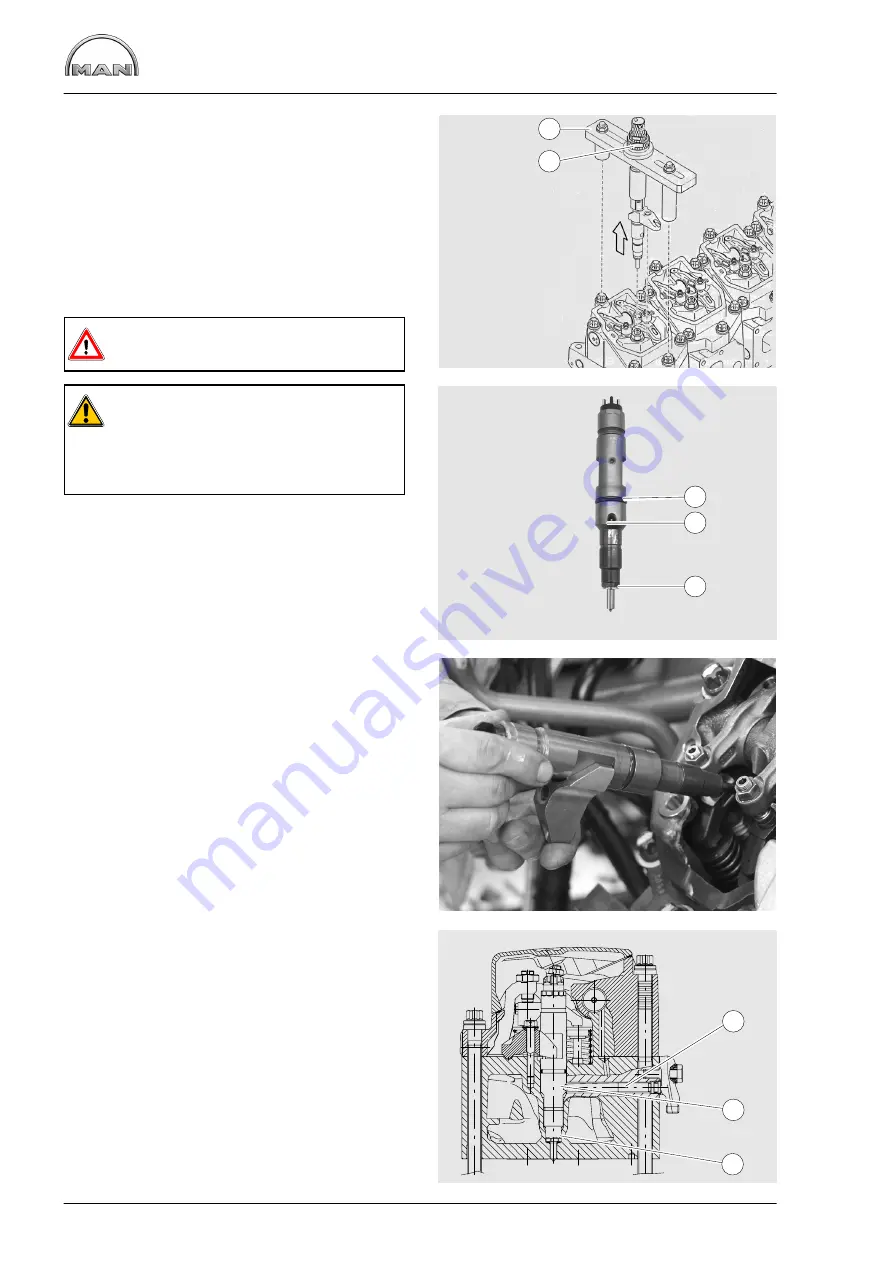
Removing and installing the injectors
34
Fig. 8
Use a support bridge
À
and extractor tool
Á
(see
page 172) to pull out the injector and pressure
flange.
D
Push the extractor tool
Á
through the support
bridge
À
over the injector, making sure that
the clamping sleeve is turned back far enough
D
Tension the clamping sleeve and pull the injec-
tor with knurled nut out of the cylinder head
Danger:
Injectors must
not
be opened!
Caution:
Immediately
close off the connection
openings of the injector with suitable caps
(see page 172) and place in the storage
sleeve.
Clean the injector seat in the nozzle bushing.
Fitting injectors
Fig. 9
Insert new O-ring
À
and new copper sealing ring
Â
.
Grease the O-ring.
Figs. 10 and 11
Insert the injector with pressure flange into the
nozzle bushing in such a way that the feed bore
hole
Á
(see also item
Á
on Fig. 9) points to the
bore hole for the pressure pipe
À
in the cylinder
head.
Press in the injector by hand as far as it will go.
Pretighten the mounting bolt for pressure flange
with
1.5 Nm
.
2
1
1
2
3
1
2
3
Summary of Contents for D 2842 LE 620
Page 1: ......
Page 2: ......
Page 20: ...Engine views D 2842 LE 620 18 7 1 2 4 3 5 6 7 1 2 4 11 9 10 8...
Page 136: ...134...
Page 137: ...135 Service Data...
Page 163: ...161 Special tools...
Page 164: ...Special tools 162 1 2 3 4 5 6 7 8 9 10 11 11 1 11 2 12 12 1 12 2 13 14...
Page 166: ...Special tools 164 15 1 15 2 15 3 15 4 15 5 1 2 7 15 6 3 4 5 6 15 7...
Page 170: ...Special tools 168 3 1 4 29 5 6 2 29 30 31 32 33 34 35...
Page 172: ...Special tools 170 36 37 38 39 42 40 41 44 2 44 1 44 43 1 43 2 43 3 43 45 46...
Page 178: ...176...
Page 179: ......
Page 180: ......


