1
2
3
4
Removing and installing valve guides
93
D
Removing and installing cylinder head, see
page 78
D
Remove and install valves, see page 87
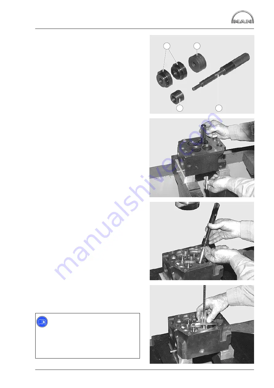
Fig. 1
Special tool for removing and installing the valve
guides and valve seats:
À
Press-in plates for valve seat inserts
Á
Spacer ring for
À
Â
Extraction and press-in punch for valve guides
and valve seats
Ã
Press-in sleeve for valve guides
Fig. 2
Press out the valve guide from the combustion
chamber side with press-in punch
Â
.
Fig. 3
Lubricate the new valve guide and press in with
the press-in punch and press-in sleeve from the
rocker arm side.
Press-in depth, see publication “Service Data”.
Fig. 4
The press
−
in depth of the valve guides is deter-
mined by the press-in sleeve.
Note:
When the valve guides have been re-
placed, the valve seats must also be re-
conditioned (refer to technical data and
manufacturer’s instructions of the valve
seat turning equipment available in the
machine shops).
1
2
4
3
Summary of Contents for D 2842 LE 620
Page 1: ......
Page 2: ......
Page 20: ...Engine views D 2842 LE 620 18 7 1 2 4 3 5 6 7 1 2 4 11 9 10 8...
Page 136: ...134...
Page 137: ...135 Service Data...
Page 163: ...161 Special tools...
Page 164: ...Special tools 162 1 2 3 4 5 6 7 8 9 10 11 11 1 11 2 12 12 1 12 2 13 14...
Page 166: ...Special tools 164 15 1 15 2 15 3 15 4 15 5 1 2 7 15 6 3 4 5 6 15 7...
Page 170: ...Special tools 168 3 1 4 29 5 6 2 29 30 31 32 33 34 35...
Page 172: ...Special tools 170 36 37 38 39 42 40 41 44 2 44 1 44 43 1 43 2 43 3 43 45 46...
Page 178: ...176...
Page 179: ......
Page 180: ......


