background image

Index

7

Preface

. . . . . . . . . . . . . . . . . . . . . . . . . . . . . . . . . . . . . . . . . . . . . . . . . . . . . . . . . . . . . . . . . . . 

Instructions

. . . . . . . . . . . . . . . . . . . . . . . . . . . . . . . . . . . . . . . . . . . . . . . . . . . . . . . . . . . . . . 

Declaration

. . . . . . . . . . . . . . . . . . . . . . . . . . . . . . . . . . . . . . . . . . . . . . . . . . . . . . . . . . . . . . . 

Nameplates

. . . . . . . . . . . . . . . . . . . . . . . . . . . . . . . . . . . . . . . . . . . . . . . . . . . . . . . . . . . . . . . 

Safety regulations

10 

. . . . . . . . . . . . . . . . . . . . . . . . . . . . . . . . . . . . . . . . . . . . . . . . . . . . . . . . . 

Commissioning and operation

14 

. . . . . . . . . . . . . . . . . . . . . . . . . . . . . . . . . . . . . . . . . . . . . 

Engine views

14 

. . . . . . . . . . . . . . . . . . . . . . . . . . . . . . . . . . . . . . . . . . . . . . . . . . . . . . . . . . . . 

First commissioning

16 

. . . . . . . . . . . . . . . . . . . . . . . . . . . . . . . . . . . . . . . . . . . . . . . . . . . . . . 

Commissioning

17 

. . . . . . . . . . . . . . . . . . . . . . . . . . . . . . . . . . . . . . . . . . . . . . . . . . . . . . . . . . 

Starting

18 

. . . . . . . . . . . . . . . . . . . . . . . . . . . . . . . . . . . . . . . . . . . . . . . . . . . . . . . . . . . . . . . . . 

Operation monitoring system

19 

. . . . . . . . . . . . . . . . . . . . . . . . . . . . . . . . . . . . . . . . . . . . . . 

Shutting down

19 

. . . . . . . . . . . . . . . . . . . . . . . . . . . . . . . . . . . . . . . . . . . . . . . . . . . . . . . . . . . 

Maintenance and care

20 

. . . . . . . . . . . . . . . . . . . . . . . . . . . . . . . . . . . . . . . . . . . . . . . . . . . . . 

Lubrication system

20 

. . . . . . . . . . . . . . . . . . . . . . . . . . . . . . . . . . . . . . . . . . . . . . . . . . . . . . . 

Fuel system

23 

. . . . . . . . . . . . . . . . . . . . . . . . . . . . . . . . . . . . . . . . . . . . . . . . . . . . . . . . . . . . . 

Cooling system

26 

. . . . . . . . . . . . . . . . . . . . . . . . . . . . . . . . . . . . . . . . . . . . . . . . . . . . . . . . . . 

Air filter

28 

. . . . . . . . . . . . . . . . . . . . . . . . . . . . . . . . . . . . . . . . . . . . . . . . . . . . . . . . . . . . . . . . . 

Checking V-belts

32 

. . . . . . . . . . . . . . . . . . . . . . . . . . . . . . . . . . . . . . . . . . . . . . . . . . . . . . . . . 

Turbocharger

34 

. . . . . . . . . . . . . . . . . . . . . . . . . . . . . . . . . . . . . . . . . . . . . . . . . . . . . . . . . . . . 

Intercooler

34 

. . . . . . . . . . . . . . . . . . . . . . . . . . . . . . . . . . . . . . . . . . . . . . . . . . . . . . . . . . . . . . 

Starter motor

34 

. . . . . . . . . . . . . . . . . . . . . . . . . . . . . . . . . . . . . . . . . . . . . . . . . . . . . . . . . . . . 

Alternator

35 

. . . . . . . . . . . . . . . . . . . . . . . . . . . . . . . . . . . . . . . . . . . . . . . . . . . . . . . . . . . . . . . 

Temporary decommissioning of engines

35 

. . . . . . . . . . . . . . . . . . . . . . . . . . . . . . . . . . . . 

Technical data

36 

. . . . . . . . . . . . . . . . . . . . . . . . . . . . . . . . . . . . . . . . . . . . . . . . . . . . . . . . . . . . 

Troubleshooting table

38 

. . . . . . . . . . . . . . . . . . . . . . . . . . . . . . . . . . . . . . . . . . . . . . . . . . . . . 

Index

40 

. . . . . . . . . . . . . . . . . . . . . . . . . . . . . . . . . . . . . . . . . . . . . . . . . . . . . . . . . . . . . . . . . . . . . 

Summary of Contents for D 2866 LE 201

Page 1: ......

Page 2: ......

Page 3: ...3 Operating Instructions MAN Industrial Diesel Engines...

Page 4: ...4...

Page 5: ...test state of the art However trouble free operation and high performance can only be achieved if the specified maintenance intervals are observed and only approved fuels lubricants and coolants are u...

Page 6: ...operation due to the sew ing machine effect in particular if they are used between parts with different rates of lin ear expansion under heat e g aluminium and cast iron and leaks may then occur Examp...

Page 7: ...16 Commissioning 17 Starting 18 Operation monitoring system 19 Shutting down 19 Maintenance and care 20 Lubrication system 20 Fuel system 23 Cooling system 26 Air filter 28 Checking V belts 32 Turboc...

Page 8: ...number Rating speed Note The manufacturer of the complete ready to use machine in which this engine is to be installed must take the further action necessary in the context of indirect safety related...

Page 9: ...in the appropriate spaces The engine type plates are on the crankcase Model delivered on installed on Engine serial number Order number MAN Nutzfahrzeuge Aktiengesellschaft Typ Motor Nr Engine No NI...

Page 10: ...peration for the first time read the oper ating instructions carefully and familiarize yourself with the critical points If you are unsure ask your MAN representative D For reasons of safety we recomm...

Page 11: ...ntenance and Care D Neither tighten up nor open pipes and hoses lube oil circuit coolant cir cuit and any additional hydraulic oil circuit during the operation The fluids which flow out can cause inju...

Page 12: ...equalization can take place D Never put cold coolant into an overheated engine See Maintenance and care D Do not add so much engine oil that the oil level rises above the max marking on the dipstick D...

Page 13: ...s are not to the expected as a result of handling used engine oil Health precautions D Avoid prolonged or repeated skin contact with used engine oil D Protect your skin by means of suitable agents cre...

Page 14: ...2866 LE 201 1 10 2 3 4 5 6 7 8 9 11 12 Fan Electro hydraulic shut off EHAB Oil filler neck Fuel strainer Air filter contamination gauge Fuel lift pump Air Cleaner Injection pump Crankcase breather 1...

Page 15: ...operation 15 13 14 15 16 17 18 19 20 1 3 Combustion air pipe to intercooler 1 7 Alternator 1 4 Combustion air pipe from intercooler 1 8 Oil filter 1 5 Water pump 1 9 Turbocharger 1 6 Tensioning pulley...

Page 16: ...id Filling with fuel Caution Fill the tank only when the engine is switched off Pay attention to cleanliness Do not spill fuel Use only approved fuels see Fuels Lubricants etc Filling in of coolant Fi...

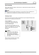
Page 17: ...l but only if at least 20 minutes have passed since the machine was switched off D Pull out dipstick D wipe it with a clean lintfree cloth D and push it in again up to the stop D Pull out dipstick aga...

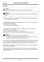
Page 18: ...signal lamp Preheating is on D Signal lamp Preheating is flashing press starter button until engine starts Caution D When engine starts release starter button immediately D lf engine does not start a...

Page 19: ...ication system must be monitored If the monitoring devices register a drop in the lube oil pressure switch off the engine immediately Shutting down Do not switch off engine immediately operation at hi...

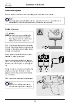
Page 20: ...th the engine at operating temperature remove the oil drain plugs on the oil sump and the oil filter bowl and allow the old oil to drain off completely Use a vessel of sufficient size to ensure that t...

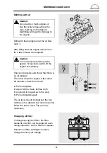
Page 21: ...diately Check oil pressure and check that there is no oil leakage Then shut down the engine After about 20 minutes check the oil level D Pull out dipstick D wipe it with a clean lintfree cloth D and p...

Page 22: ...r The oil is hot and under pressure when the drain plug is opened Risk of burns and scalds D After releasing the clamping bolts remove filter bowls D Renew filter cartridges Thoroughly clean all other...

Page 23: ...st be made to the injection pump If the lead seal is damaged the war ranty on the engine will become null and avoid Faults We urgently recommend that you have faults in the injection pump rectified on...

Page 24: ...f accordingly Change over fuel filter Where the changeover type filter is installed the servicing procedure is for the filter side requiring to be shut off with the engine running During continuous op...

Page 25: ...fuel system Note To bleed the fuel system switch on the ignition so that the EHAB will be open The single box type filter has only one bleed screw An arrow on the filter head indicates the direction...

Page 26: ...pose of it in accor dance with regulations Drain coolant as follows but only when the engine has cooled down D Briefly open cap large cap on the filler neck of the expansion tank for pressure compensa...

Page 27: ...must be added at the filler neck only Do not put cold coolant into an engine which is warm from operation Ensure that the ratio of water to anti freeze is correct D Remove cap D Fill in the coolant s...

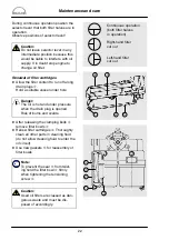
Page 28: ...ne is switched off 1 2 3 4 5 7 6 Dust collector The dust collector must be emptied at reg ular intervals The collector should never be more than half full of dust When the two retainers have been fold...

Page 29: ...anged When the filter has been changed pull the return knob The red field then disap pears 1 2 Display filter service is due Display filter is ready for operation Changing the filter cartridge Caution...

Page 30: ...f the car tridge Blow the cartridge out from the inside with dry compressed air max 5 bar by mov ing the pipe up and down inside the car tridge until no more dust is released Checking the cartridge Wh...

Page 31: ...used Safety cartridges must be changed at the latest after being in use for two years if after the main cartridge has been serviced changed the contamination gauge responds again immediately if the m...

Page 32: ...ve upwards If pressure is maintained after the spring has disengaged a false reading will be obtained Reading of tension D Read of the tensioning force of the belt at the point where the top surface o...

Page 33: ...ions D Retighten lock nut and fixing bolts To replace the V belts loosen lock nut and swing alternator inwards Fan Tensioning pulley D Remove fixing bolts D Remove lock nut D Adjust nut until V belts...

Page 34: ...as possible the intercooler must be cleaned at certain intervals Starter motor Check that the electric cables are properly fastened and that contacts and plug connec tions are secure In engines fitte...

Page 35: ...iately and remedy the fault in the electrical system D Do not run the engine unless the battery charge control is in satisfactory order D Do not short circuit the connections of the alternator with th...

Page 36: ...7 cm3 Compression ratio 15 5 1 Rating see engine nameplate Firing order 1 5 3 6 2 4 Valve clearance cold engine Intake 0 50 mm Exhaust 0 50 mm Valve timing Intake opens 23 before TDC Intake closes 12...

Page 37: ...min constant 16 12 Engine lubrication Force feed Oil capacity in oil sump litres min max deep 24 l 30 l deep on board unit 14 l 18 l shallow 16 l 20 l Oil change quantity with filter deep 33 l deep o...

Page 38: ...ensation in fuel D D D D Air filter clogged D Electric circuit interrupted D Batteries flat D Starter solenoid switch defective D D D D D Start of delivery not correct incorrectly set D Injection nozz...

Page 39: ...valves on expansion tank radiator defective or leaking D Temperature gauge defective D Coolant pipes leaking blocked or twisted D Oil level in sump too low D Engine temperature too high D Oil filter...

Page 40: ...ling in of coolant 16 First commissioning 16 Fuel filters 24 Changing fuel filter 24 25 Fuel system 23 25 I Injection pump 23 Instructions 6 Intercooler 34 L Lubrication system 20 22 M Maintenance and...

Page 41: ......

Page 42: ......

Reviews: