5
6
7
8
Removing and installing the crankshaft
107
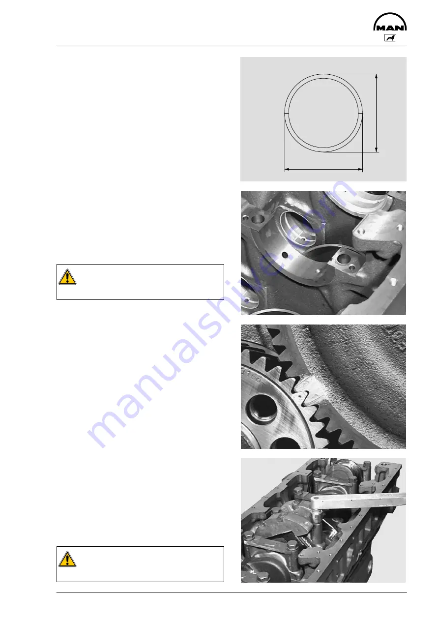
Check the spread of the bearing bushes
Fig. 5
Place the bearing bushes together on a level sur-
face. Measure and note down dimensions
“A”
and
“B”
.
Spread dimension = A - B
Install the crankshaft
Fig. 6
Clean the oilways in the crankcase and in the
crankshaft with dry compressed air.
Thoroughly clean the bearing bushes and journals.
Insert the bearing bushes in the crankcase, obser-
ving the numbering.
Caution:
If new bearing bushes are used, pay at-
tention to the corresponding repair level.
Fig. 7
Oil the bearing surfaces of the bearing bushes and
insert the crankshaft.
In doing so, note the marking of the crankshaft and
camshaft toothed wheel.
Fig. 8
Check bearing cover bolts for max. permitted
length (see “Service Data”).
Removed bolts can be reused if the max. permit-
ted length is not exceeded.
Assemble the bearing caps with the associated
bearing shells in accordance with the installations
sequence.
Oil the contact surfaces of the bearing shells and
fit the bearing caps.
Insert the bearing cap bolts and tighten to speci-
fied torque in stages from the inside outwards.
Final tightening according to rotation angle me-
thod.
Check that the crankshaft runs smoothly.
Caution:
Damaged bearing covers cannot be re-
placed on an individual basis.
A
B
Summary of Contents for D 2866 LUE 605
Page 1: ......
Page 2: ......
Page 14: ...Notes 12...
Page 19: ...Memoranda 17...
Page 20: ...Engine views 18 Engine views 3 4 2 1 7 6 5 8 11 10 9...
Page 68: ...Memoranda 66...
Page 133: ...131 Service Data...
Page 157: ...155 Special tools...
Page 158: ...Special tools 156 2 3 4 5 6 7 8 1 6 1 6 2 6 3 9 1 9 2 9 3 9...
Page 162: ...Special tools 160 21 22 25 25 2 24 25 1 26 27 1 27 2 27 20 1 19 2 19 1 20 2 19 20 23 28...
Page 164: ...Special tools 162 30 31 32 1 32 32 2...
Page 167: ...Special tools 165 Pressing mandel for cap dia 62 1 mm Pressing mandel for cap dia 50 1 mm...
Page 170: ...Notes 168...
Page 173: ......
Page 174: ......


