Repairing coolant pump with high-temperature and
low-temperature parts D 2866 LUE 605
54
Replacing coolant pump during repair work only in event of identified leakage
The design of the coolant pump mechanical cassette seal permits small amounts of coolant to pass
through it.
This coolant passing through results in a trace of drained coolant below the drain bore.
This trace of drained coolant does not mean that the coolant pump has to be replaced.
For this reason, before replacing or repairing a coolant pump, ascertain
D
whether the cooling circuit shows visible and recurring signs of coolant loss; if yes
D
whether the coolant loss is caused by spillage from the expansion tank (e.g. too full) or by other leaka-
ges from hoses, radiator etc.
Coolant pumps may only then be replaced if dripping water can clearly be seen while the engine is running
or after it has been turned off.
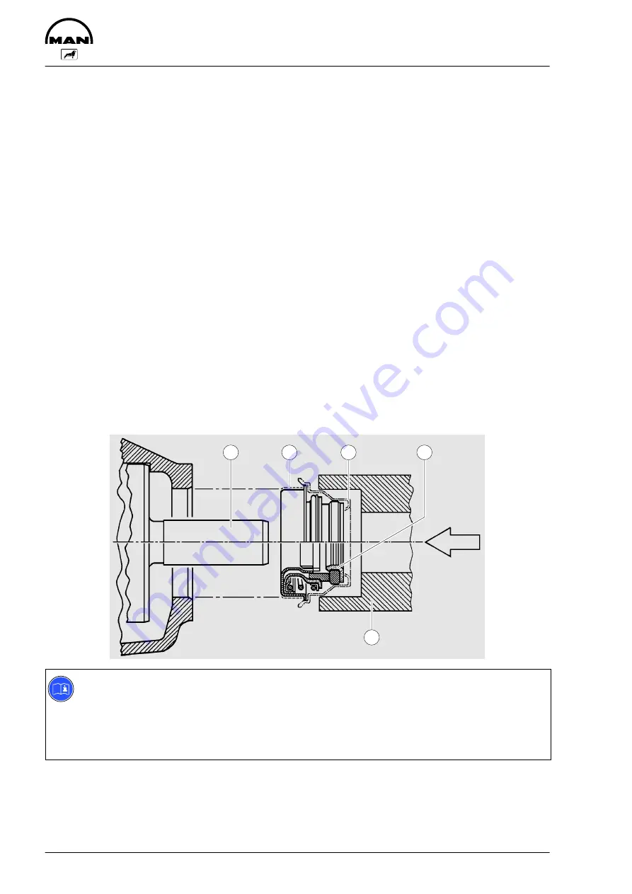
Installation note for mechanical seal:
Install mechanical seal while ”wet”, i.e. to install it, coat holding sleeve and water pump shaft with a mixture
of either 50% water and 50% cleaning spirit or 40% to 50% antifreeze agent as per MAN 324 and water.
Other antiseize agents must not be used.
Because the seal on collar
Á
is coated with sealing paint, no sealing paint needs to be applied if the loca-
ting bore in the coolant pump housing is in perfect condition.
If the bore shows even the slightest scoring or other minor damage, a sealing bead of Dirko-Transparent,
Part No. , must be applied to collar
Á
.
Fit the seal with a plastic transportation cap onto shaft
À
and use installation tool Ä to press it in until the
tool contacts the housing. Remove the plastic cap.
1
2
3
4
5
Note:
Tests have shown that most cases of damage to the coolant pump can be attributed to the use of
unsuitable coolants.
Only
the anticorrosion and antifreeze agents expressly approved by MAN Nutzfahrzeuge AG as
per MAN norm 324 (see brochure “Fuels, Lubricants, Coolants for and MAN Diesel Engines”)
guarantee faultless operation
Summary of Contents for D 2866 LUE 605
Page 1: ......
Page 2: ......
Page 14: ...Notes 12...
Page 19: ...Memoranda 17...
Page 20: ...Engine views 18 Engine views 3 4 2 1 7 6 5 8 11 10 9...
Page 68: ...Memoranda 66...
Page 133: ...131 Service Data...
Page 157: ...155 Special tools...
Page 158: ...Special tools 156 2 3 4 5 6 7 8 1 6 1 6 2 6 3 9 1 9 2 9 3 9...
Page 162: ...Special tools 160 21 22 25 25 2 24 25 1 26 27 1 27 2 27 20 1 19 2 19 1 20 2 19 20 23 28...
Page 164: ...Special tools 162 30 31 32 1 32 32 2...
Page 167: ...Special tools 165 Pressing mandel for cap dia 62 1 mm Pressing mandel for cap dia 50 1 mm...
Page 170: ...Notes 168...
Page 173: ......
Page 174: ......


