Commissioning and operation
72
Alarm and limit value display
Dynamic limit value display
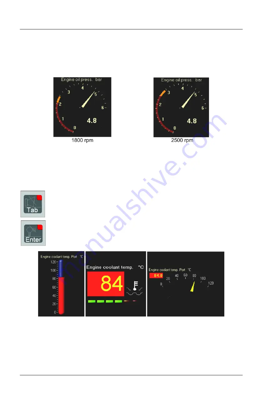
Limit values depending on the speed are represented dynamically by the monitoring system. In the follow
ing illustration, the speed was changed at constant oil pressure. The rise in the limit value can be recog
nised with increasing speed.
Figure: dynamic limit value display on the oil pressure gauge
Graphical alarm display and alarm acknowledgement
When a state of alarm has been reached, the corresponding instrument starts flashing. In the event of an
alarm, the instrument flashes until the alarm state is acknowledged. Two keys to the right of the display are
used for the acknowledgement.
Function: acoustic acknowledgement or deactivation of the internal horn. All monitoring devi
ces within the system are acknowledged on operation.
Function: Visual acknowledgement, which means that all flashing alarms switch to conti
nuous light if they have previously been acknowledged acoustically. All monitoring devices
within the system are acknowledged on operation.
Figure:
various versions of the “Coolant temperature" instrument flashing in the event of an alarm


