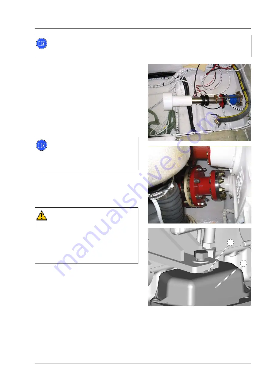
Aligning an engine with flange−mounted gearbox
29
Note:
The mounts are pre−compressed at the factory by the shipping locks. For this reason it is not
necessary to preload the resilient mounts before the alignment.
Provisionally aligning drive line
D
Place the drive line and the resilient mounts
onto the engine foundation using suitable crane
lifting equipment.
D
Raise the propeller shaft by hand at the
coupling flange as far as possible.
Half the angle between the highest and lowest
positions of the coupling flange provides the
correct height for the gearbox output flange.
This ensures that the propeller shaft can be
correctly centred.
Note:
A resilient propeller shaft coupling between
gearbox output flange and propeller shaft
flange compensates minor offset and
reduces vibrations.
D
Align gearbox output flange and propeller shaft
flange flat with the aid of suitable surfaces.
D
Adjust the height
À
of the engine mounts
Á
. In
so doing, ensure that the mounts are equally
compressed on both sides of the engine.
Caution:
The max. height adjustment of all mounts
is 10 mm.
This adjustment height must not be
exceeded. Larger differences in height
must be compensated for with metal
shims.
The less the height is adjusted, the more
room for later adjustments.
1
2
Summary of Contents for V12-1800
Page 1: ......
Page 2: ......
Page 12: ...Planning of engine installation 10 V12 1800 1 2 3 4 5 V8 1200 6 7 8 9 4 10 11...
Page 78: ...Notes 76...
Page 79: ...77 Appendix...
Page 80: ......
Page 91: ......
Page 92: ......


