18
SS-M05_Marine | 1.01.00
www.mc-techgroup.com
Do not use the gas conditioning device at temperatures other than
those specified. This avoids false alarms and ensures the operational
safety of the gas conditioning system and the additionally connected
analyzer.
Downstream analysers and the unheated Teflon tubing must always
be operated at temperatures well above the specified gas output dew
point of +5 °C.
Unheated gas sample lines must be installed with a slope down to the
cooler. Condensate pre-separation is then not necessary.
11.1 CONNECTING THE SAMPLE GAS LINE
Note
Do not mix up connections. The upper heat exchanger connection is the
inlet, the side heat exchanger connection is the outlet and the lower heat
exchanger connection is the condensate outlet.
The sample gas line is connected to the inlet of the external heat exchanger. The heated part of the
sample gas line should end approx. 30 cm in front of the heat exchanger.
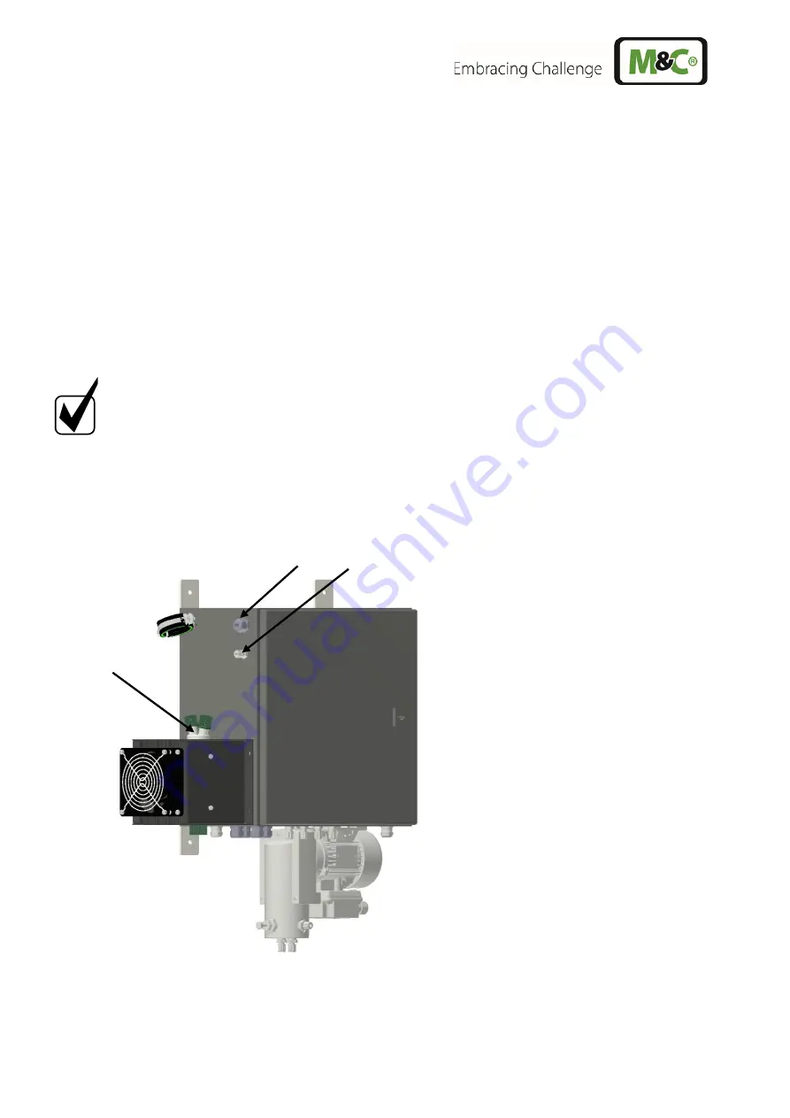
The electrical connection of the sample gas line is made via the cable gland K1 at the upper left corner
of the SS-M05 system cabinet. The outlet of the heat exchanger must be connected to media
connection 1.
Cable gland K1
Media connection 1
Heat exchanger inlet (A1) and outlet
Figure 3
Sample gas line connection
Summary of Contents for 03G6000
Page 44: ...44 SS M05_Marine 1 01 00 www mc techgroup com Figure 13 Wiring diagram part 1 ...
Page 45: ...www mc techgroup com SS M05_Marine 1 01 00 45 Figure 14 Wiring diagram part 2 ...
Page 46: ...46 SS M05_Marine 1 01 00 www mc techgroup com ...
Page 47: ...www mc techgroup com SS M05_Marine 1 01 00 47 ...
Page 48: ...48 SS M05_Marine 1 01 00 www mc techgroup com ...


