www.mc-techgroup.com
SS-M05_Marine | 1.01.00
23
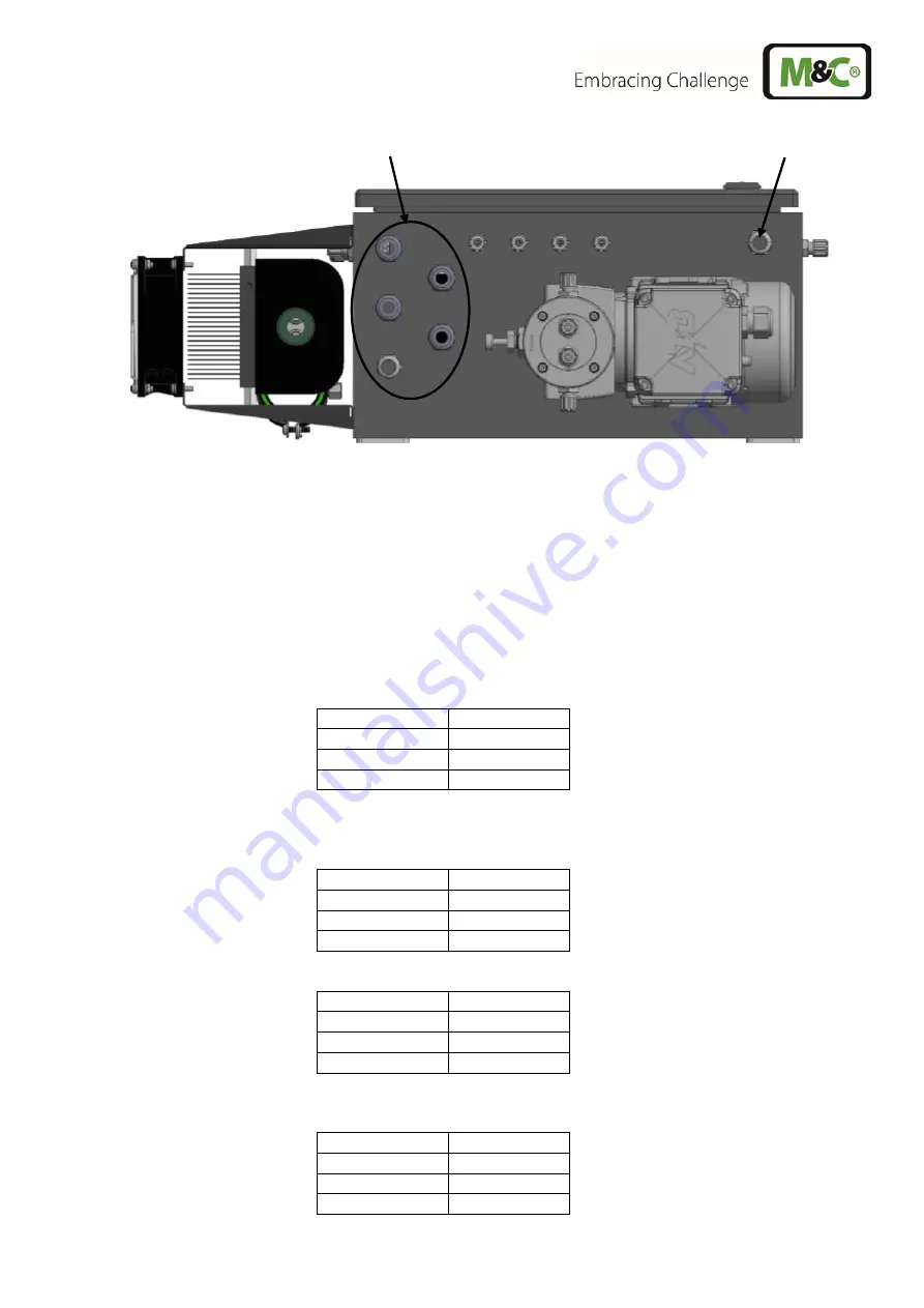
Cable glands
Cable gland for sample gas pump
Figure 6
Cable glands
12.3 ELECTRICAL INSTALLATION
Carry out the electrical installation (the electrical fuses of the gas conditioning device must be switched
off):
1. Connect the mains power supply (see –X1 in circuit diagram).
a. Terminal X1:
Position
Wire
1
L
11
N
18
PE
2. Use shielded cables to connect the following alarms: Liquid alarm and Flow alarm, see –X2 in
circuit diagram).
a. Liquid alarm, terminal X2:
Position
Wire
1
MC
2
NO
3
NC
b. Flow alarm, terminal X2:
Position
Leiter
4
MC
5
NO
6
NC
3. Connect the solenoid valve –Y1 (see –X3 in circuit diagram).
a. Solenoid valve, 24 V auto cal, terminal X3:
Position
Leiter
1
+24 V
2
0 V
3
PE
Summary of Contents for 03G6000
Page 44: ...44 SS M05_Marine 1 01 00 www mc techgroup com Figure 13 Wiring diagram part 1 ...
Page 45: ...www mc techgroup com SS M05_Marine 1 01 00 45 Figure 14 Wiring diagram part 2 ...
Page 46: ...46 SS M05_Marine 1 01 00 www mc techgroup com ...
Page 47: ...www mc techgroup com SS M05_Marine 1 01 00 47 ...
Page 48: ...48 SS M05_Marine 1 01 00 www mc techgroup com ...


