background image


www.mc-techgroup.com 

Temperature controller 70304  |  1.02.00 

19


17.1


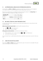
ADJUSTING SIGNAL TYPE AND TEMPERATURE RANGE 

To adjust the signal type and temperature range:  


PGM-key, 

USEr

 up to 

Conf

, PGM-key, 

 up to 

OutP

, PGM-key, 

 up to 

OutA

, PGM-key, 

Out6

, PGM-key, 

Fnct


SiGn

, PGM-key, 

SiGn

 blinking, with 

 or 

 choose signal type:  

0 = 0-10 V 

1 = 2-10 V 

2 = 0-20 mA 

3 = 4-20 mA (factory setting) 


Takeover of the adjusted value takes place after 2 seconds. 


 up to 

0Pnt

 (zero point of the temperature range): PGM-key, 

0Pnt

 blinking, with 

 or 

 adjust zero point (0,0 

= factory setting). 


 up to 

End

 (end point of the temperature range): PGM-key, End blinking, with 

 or 

 adjust end point (200,0 = 

factory setting). 


18


DECOMMISSIONING 


 Note


The place of installation of the temperature controller must be protected from frost also 

in the time in which the unit is deactivated

.


No particular measures are necessary for brief decommissioning of the temperature controller. 


19


MAINTENANCE 

Before carrying out maintenance work, the system and process-specific safety measures must be observed! 


  Warning 


High voltage. 

Before opening the housing, isolate the temperature controller from the sup-

ply!


The temperature controller does not require any special maintenance. 


The temperature controller should be cleaned with compressed air from time to time depending on the degree 

of pollution of the ambient air.


Summary of Contents for 70304

Page 1: ...Electronic Temperature Controller 70304 70304 2 Instruction Manual Version 1 02 00...

Page 2: ...he addresses in the appendix of this manual For additional information about our products and our company please go to M C s website www mc techgroup com There you will find the data sheets and manual...

Page 3: ...16 15 Comissioning 16 15 1 Entry and check of controller parameters 16 15 2 Self optimising PID action of control circuit 17 15 3 Commissioning with heated foreign components 17 16 Low temperature ala...

Page 4: ...roduct by qualified per sonnel Please follow all instructions and warnings closely Please read this manual carefully before commissioning and operating the device If you have any questions re garding...

Page 5: ...ing the equipment it must be switched off and hold no voltages This also applies to any external control circuits that are connected The device is only to be used within the permitted range of tempera...

Page 6: ...illed Caution This means that minor physical injuries may occur in case the respective safety measures are not fulfilled Caution Without the warning triangle means that a material damage may occur in...

Page 7: ...ave an adjustable sensor input for all common temperature sensors and they can be used as an programmable two or three step or continious and self optimizing controller with PID structure 7 RECEIPT OF...

Page 8: ...order to change values in order to change values Exit key in order to leave the levels 2 Active Setpoint Factory setting SP1 5 Indication yellow for Switch status of binaryoutputs 1 6 display lights...

Page 9: ...4 1 02 00 9 9 DIMENSIONS AND INSTALLATION 45 0 6 0 45 0 6 0 Figure 2 Mounting cutout for controller 70304 for front panel mounting Figure 3 Housing and mounting dimensions for controller 70304 for fro...

Page 10: ...ller 70304 1 02 00 www mc techgroup com PGM EXIT 1 7 1 6 N 3 2 L 3 1 3 5 3 4 3 8 3 7 2 8 2 6 2 4 2 3 2 2 110 122 55 37 5 5 75 4 5 61 25 75 Figure 4 Housing and mounting dimensions for controller 70304...

Page 11: ...onditions 90 r H dew not allowed Electrical connections Terminals 1 5 mm2 Power supply 110 240 V 10 15 48 63 Hz 8 VA Housing material Synthetic material Housing version Front panel mounting Rail mount...

Page 12: ...contini ous cutoff 3 A 250 V AC resistive load Opens exceeding the ac tual value by 10 C 2 closed 3 8 3 4 Alarm 1 Low temperature 3A 250 V AC resistive load Closes reaching the set value 10 C 1 closed...

Page 13: ...lace Max low temperature difference to the setpoint Lo t factory setting 10 C In case of falling below an alarm signal takes place Limit comparator Lfun factory setting 2 for controller with ramp func...

Page 14: ...THE LEVEL INHIBIT To remove the level inhibit act as follows Standard display below setpoint up actual value has to be visible Press key PGM and simultaneously for 5sec display Code 3 all levels are l...

Page 15: ...he standard display press EXIT key 2 x Figure 5 Menu structure Lin Exit Time out 2 min SP Setpoint ALSE Excess temperature with lock Lo t Low temperature alarm LFun Limit comparator function Fnct Func...

Page 16: ...larm which will permanently deactivate the heating circuit For restart Let cool down the device below the new setpoint Press EXIT and key or Reset of the low temperature alarm by switching of and on o...

Page 17: ...ly for longer than 2 seconds The word tUnE now flashes in the setpoint value display and the self optimising function is activated Self optimization has finished when the display changes to the standa...

Page 18: ...XCESS OR LOW TEMPERATURE ALARM In order to restart the unit after a temperature alarm with permanent deactivation the cause of the alarm must initially be remedied With not programmed ramp functions a...

Page 19: ...perature range PGM key End blinking with or adjust end point 200 0 factory setting 18 DECOMMISSIONING Note The place of installation of the temperature controller must be protected from frost also in...

Page 20: ...ded spare parts S Spare parts Recommended quantity being in operation years V E T 1 2 3 01B8401 Electronic PID temperature controller type 70304 with self optimising function front mounting enclosure...

Reviews: