www.mc-techgroup.com
Temperature controller 70304 | 1.02.00
17
15.2
SELF-OPTIMISING (PID ACTION) OF CONTROL CIRCUIT
The controllers type
70304 and 70304.2
include the option of self-optimising. For the initial operation of all
M&C
components, this is necessary.
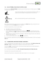
Note
For self-optimising of the control circuit, the heating of the respective M&C com-
ponent must be reconnected to the appropriate controller terminals.
Warning
Before connecting the heating, isolate the unit from the supply!
Before self-optimizing firstly the ramp function has to be deactivated (
Fnct = 0
) and the parameter for the limit
comparator has to be changed (
Lfun = 6
). See also chapter 13.
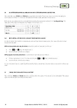
The self-optimising function can be activated as follows:
•
After cable connection, switch on the supply.
•
When the actual value (top display, red indicator)
reaches the setpoint value (bottom display, green indicator), press
+
keys simultaneously for longer
than 2 seconds. The word ”
tUnE
” now flashes in the setpoint value display and the self-optimising function is
activated.
•
Self-optimization has finished when the display changes to the standard display. The time of self-optimizing
depends on the control circuit.
•
To cancel the self-optimization press the keys
+
simultaneously.
After self-optimization reactivate the ramp function (
Fnct = 1
) and reset the parameter for the limit comparator
(
Lfun = 2
).
15.3
COMMISSIONING WITH HEATED FOREIGN COMPONENTS
Commissioning takes place as described in chapters 16.1 and 16.2. The parameters for
SP
,
ALSE, Lo-t, Lfun, Fnct,
rASL, SenS
and
Lin
must be entered for the respective component (see chapter 12 and 13).
The parameter
rASL
must be determined. For this purpose the time for heating the unit until the setpoint tem-
perature is reached must be measured.
This is then followed by (empirical value):
rASL = 0.8 (setpoint temperature/rate of temperature rise)
The calculated rASL value must be entered rounded.
After entering the parameters a self optimization, described in chapter 15.2, has to be operated.


