background image


12 

MP30  |  1.00.01 

www.mc-techgroup.com


11.3 

PNEUMATIC 


N O T E !


Components  to  be  connected  to  the  pump  must  conform  to  the  pneumatic 
data of the pump.


Remove safety stoppers from threaded gas connections (thread size G1/8”). 


  Accessories such as threaded hose couplings must be screwed into the threaded connection with 

sealing tape (the use of sealing tape is unnecessary when using 

M&C 

couplings). 


  Connect suction and pressure pipe. 


N O T E !


Do  not  interchange  hose  connections  for  sample  gas  inlet  and  outlet;  the 
connections are appropriately marked. 


After connecting all pipes, they must be checked for tightness.


When connecting the hoses to optional threaded hose couplings, the following should be noted: 


N O T E !


The  tightness  of  the  connection  can  only  be  ensured  when  the  connecting 
hose has a straight terminating edge (use of a hose cutter).


  Loosen the swivel nut of the clamping ring by turning anticlockwise; it must be ensured that the nut 

is carefully removed from the coupling, so that the clamping ring lying loosely in the clamping ring 
is not lost.


  Slide the swivel nut on to the connecting hose.


  Slide the clamping ring with the thicker part pointing towards the nut on to the connecting hose.


  Fit the hose on to the supporting nipple in the coupling;


  Tighten the swivel nut hand-tight.


The hose is not connected non-slip and pressure-proof. 
 

Optional threaded couplings for DN 4/6 or DN 6/8 can be obtained through M&C 


  Route the suction and pressure pipe so that no condensate can flow into the pump. 


Summary of Contents for MP Series

Page 1: ...Analytical Diaphragm Pump Series MP MP30 Instruction Manual Version 1 00 01...

Page 2: ...sses are to be found in the annexe to this operating manual Please also contact our homepage www mc techgroup com for further information about our products There you can read or download the data she...

Page 3: ...ata 9 9 Dimensions 10 10 Receipt and storage 10 11 Installation information 10 11 1 Mechanical 11 11 2 Electrical 11 11 3 Pneumatic 12 12 Commissioning 13 13 Decommissioning 14 14 Maintenance 14 14 1...

Page 4: ...riate transportation correct storage as well as professional installation and maintenance work All necessary information a skilled staff will need for appropriate use of this product are given in this...

Page 5: ...re opening the equipment it must be switched off and hold no voltages This also applies to any external control circuits that are connected The device is only to be used within the permitted range of...

Page 6: ...minor physical injuries may occur in case the respective safety measures are not fulfilled C AR E Without the warning triangle means that a material damage may occur in case the respective safety mea...

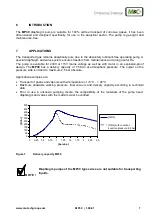
Page 7: ...on proof design The MP30 has a delivery capacity of 7 5l min at atmospheric pressure The output on the pressure side is limited to maximum 2 5 bar absolute Application examples are Transport of gases...

Page 8: ...not be used in areas subject to explosion hazards or for transporting a potentially explosive medium When transporting toxic media system specific and safety relevant regulations must be observed MAC...

Page 9: ...0 Delivery capacity max 7 5 l min Operating pressure 0 14 to max 2 5 bar abs Gas temperature 5 C to 40 C Ambient temperature 5 C to 40 C Storage temperature 15 C to 60 C Gas connections G1 8 i DIN ISO...

Page 10: ...ceipt and check the delivery against the delivery note Check the contents for possible transport damage and immediately notify the transport insurer of any damage NOTE The diaphragm pump should be sto...

Page 11: ...s must be installed in such a way that the impeller is able to draw in sufficient cooling air The pumps should be installed at the highest point in the system and or with the pump head pointing downwa...

Page 12: ...hose couplings the following should be noted NOTE The tightness of the connection can only be ensured when the connecting hose has a straight terminating edge use of a hose cutter Loosen the swivel n...

Page 13: ...king pressure of the pump is not exceeded With the pump stationary normal atmospheric pressure must be established in the pipes Diaphragms and valve plates are the only wearing parts of the pumps Wear...

Page 14: ...process specific safety measures must be observed W AR N I N G Dangerous voltage Before working on the diaphragm pump the same must be safely isolated from the supply and disconnection from the suppl...

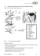
Page 15: ...making a continuous line with a felt tip pen Loosen four head screws 5 Remove pressure plate 15 head cover 4 and intermediate plate 1 from pump housing Loosen four fixing screws in impeller cover 13 a...

Page 16: ...on by lightly moving the valve seat Fit sealing rings 3 in intermediate plate 1 Join head cover 4 and intermediate plate 1 together felt tip pen mark must be in alignment and check centred seat throug...

Page 17: ...rheating Delivery capacity pressure or vacuum too low Diaphragms or valve plates worn Replace worn parts see 14 ff Problem Indication Possible cause Check Remedy Initially compare reached pump capacit...

Page 18: ...nd on specific operating conditions The recommended quantities are based on experience and are not binding Diaphragm Pump Type MP30 C consumable parts S spare parts Recommended quantity MP30 being in...

Reviews: