background image


6


2-5.1.2-ME 


Gas sampling and conditioning technology


USED TERMS AND SIGNAL INDICATIONS  


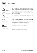
  D A N G E R !  

This means that death, severe physical injuries and/or important 
material damages will occur in case the respective safety measures 
are not fulfilled.   


  W A R N I N G !  

This means that death, severe physical injuries and/or important 
material damages may occur in case the respective safety 
measures are not fulfilled.  


  C A R E !  

This means that minor physical injuries may occur in case the 
respective safety measures are not fulfilled.  


C A R E !  

Without the warning triangle means that a material damage may 
occur in case the respective safety measures are not met.  


A T T E N T I O N !  

This means that an unintentional situation or an unintentional status 
may occur in case the respective note is not respected.  


N O T E !  

 
These are important information about the product or parts of the 
operating manual which require user’s attention.  


SKILLED STAFF 

These are persons with necessary qualification who are familiar with 
installation, use and maintenance of the product.  


Summary of Contents for TRH

Page 1: ...Gas sampling and conditioning technology 2 5 1 2 ME Operating Manual Electronic Temperature Controller Type TRN TRN 20 TRM TRM 20 TRH and TRH 20 ...

Page 2: ...act addresses are to be found in the annexe to this operating manual Please also contact our homepage www mc techgroup com for further information about our products There you can read or download the data sheets and operating manuals of all M C products as well as further information in German English and French This Operating Manual does not claim completeness and may be subject to technical mod...

Page 3: ... signal indications 6 6 Application 7 7 Technical data 7 8 Description 7 9 Receipt of goods and storage 8 10 Installation instructions and dimensions 8 11 Electrical connections 9 12 Initial starting 9 13 Closing down 10 14 Maintenance and repair 10 15 Appendix 10 List of Illustrations Figure 1 Dimensions TR 8 Figure 2 Connector pin assignment of the multipole socket 9 ...

Page 4: ...ate transportation correct storage as well as professional installation and maintenance work All necessary information a skilled staff will need for appropriate use of this product are given in this operating manual 2 DECLARATION OF CONFORMITY CE Certification The product described in this operating manual complies with the following EC directives EMV Instruction The requirements of the EC directi...

Page 5: ...tages Before opening the equipment it must be switched off and hold no voltages This also applies to any external control circuits that are connected The device is only to be used within the permitted range of temperatures and pressures Check that the location is weather protected It should not be subject to either direct rain or moisture The device must not be used in hazardous areas Installation...

Page 6: ...eans that minor physical injuries may occur in case the respective safety measures are not fulfilled C A R E Without the warning triangle means that a material damage may occur in case the respective safety measures are not met A T T E N T I O N This means that an unintentional situation or an unintentional status may occur in case the respective note is not respected NOTE These are important info...

Page 7: ...power and 5 pin coupling socket for connection of the heated line controlled mains voltage ON OFF and PT100 sensor Power supply 230V 10 50 60Hz Housing version international protection type Wall mounting housing IP 66 EN60529 Housing material polycarbonate Dimensions in mm see diagram 1 Weight 1 2 kg 8 DESCRIPTION The TR series on off electronic temperature controller is mounted in a wall mounting...

Page 8: ...ully from the packing and check the articles for completeness against the packing list Check the goods for any damage during transportation and if required inform your shipping insurance immediately of the damage found NOTE The controller should be stored in a weather protected and frost free area 10 INSTALLATION INSTRUCTIONS AND DIMENSIONS Figure 1 Dimensions TR ...

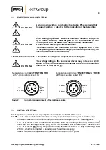
Page 9: ...of TR N M H and must be a maximum of 4 600 watt in the case of TR N M H 20 Temperature controllers TRN TRM TRH Temperature controllers TRN 20 TRM 20 TRH 20 with 7 pin coupling socket 10A with 5 pin coupling socket 20 A Figure 2 Connector pin assignment of the multipole socket 12 INITIAL STARTING The temperature control device may only be used with the stated PT 100 sensor The TR series temperature...

Page 10: ...aches the desired operating temperature 13 CLOSING DOWN No special measures are to be taken for closing down the equipment 14 MAINTENANCE AND REPAIR The controller TR are working maintenance free for a long period of time In case the controller is defective please send the device to M C for repair NOTE The controller is equipped with a sensor break protection that in case of need cuts off the unit...

Reviews: