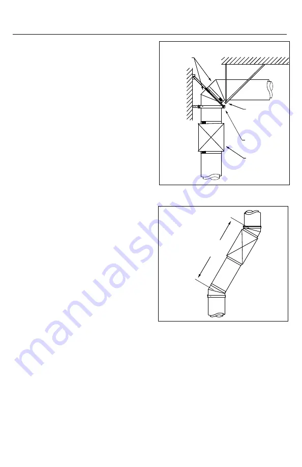
15
Figure 17
provides increases of one, two or three size.
The height of the fitting varies depending on
the diameters to be increased (see Figure 17).
3. The tapered increaser have the same load
strength as a standard length, but the step
increaser is a non-structural part and must be
protected from axial and lateral load.
ELBoWS
1. Elbows are used for changes in direction in
horizontal or vertical portions of a
chimney system.
2. All elbows feature the standard joint
assembly as described in Section A - Chimney
and Fitting Assembly.
3. Elbows are used in combination to make
different angles ranging from 3° to 90° in
horizontal and vertical breechings of the
chimney system.
4. Elbows are not designed to take bending
loads and must be structurally supported
(see Figure 17). Structural parts such as
posts or beams may also be needed to hold
chimney supports in position.
oFFSEtS
1. Sloped or horizontal offsets in the vertical
portion of a chimney above the breeching should
be avoided except where absolutely necessary.
2. Sloped offsets require more expansion joints
and secure bracing above and below elbows.
3. With solid fuel burning appliance, the
slope must not be greater than 30° from the
vertical. Appliances which are capable of
burning solid fuel or are convertible to solid
fuel are limited to the same 30° slope.
4. The length of the offset is determined
by strength considerations. The maximum
dimension between supports, given as the
MHS dimension in Table 7, is applicable to
all horizontal and sloped orientations (see
Figure 18)
5. The minimum offset is accomplished with
two elbows directly connected to each other
(see Figure 33 and Table 9).
6. With frequent re-support, there is no structural
Figure 18
or operating limit to the length of horizontal or
sloped portions of model DIS chimney, providing
the system meets the capacity, pressure drop of
available equipment.
7. The carrying capacity of supports and their
structural attachments must take into account
the weight of the offset plus whatever vertical
chimney is carried by that support.
8. Height limits for supports ar tabulated in
Section A of these instructions.
2x 45°
Elbow
Anchor Plate
and Frame
Wall Support
Expansion
Length
MHS


