17
the anchor plate assembly must be coated
with inner joint sealant.
6. There are two ways of assembling parts on
the support. You may choose your method
depending on your situation.
6.1 The first method consists of assembling
two parts and the anchor plate on the side
and then installing this assembly on the
support structure. This method is easier
and faster to install, but requires enough
clearance to insert the complete assembly
through the support structure opening.
If there is a tee or elbow upstream of the
anchor plate, you may not have enough
clearance. Also consider the weight of the
assembled parts and make sure you have a
safe manner of lifting the assembly.
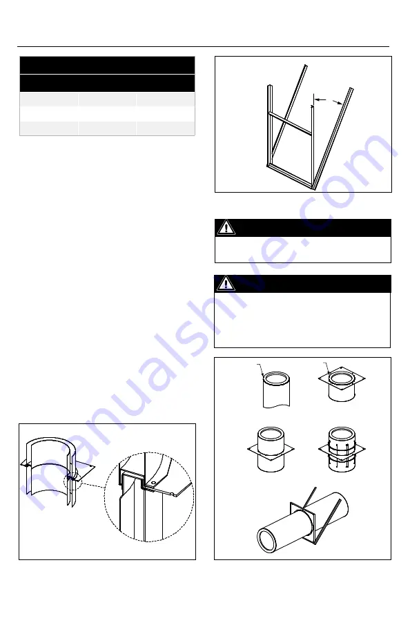
Installation Steps for First method (refer to
Figure 22)
1. Place the part that will be upsteam of the
support on the floor.
2. Apply a bead of inner joint sealant on the
male coupling flange.
Figure 20
Figure 21
Important
If bracing is used, minimum “X” angle is 30°.
If there is no bracing, the framework
must be attached to structural members to
provide equivalent rigidity.
Important
Height Limits - See Section a, table 6 for
maximum support height of Anchor Plate (AP).
Figure 22
Table 12
Bracing DIS/DAS
I.D.
Framework
Bracing
5" - 20"
3" x 2" x 3/16"
2" x 2" x ¼"
22" - 36"
4" x 2" x ¼"
3" x 3" x ¼"
"X"
Sealant
Bead
Sealant
Bead
Method #1-
Step 1 and 2
Method #1-
Step 3 and 4
Method #1-
Step 5
Method #1-
Step 6
Method #1-
Step 7


