32
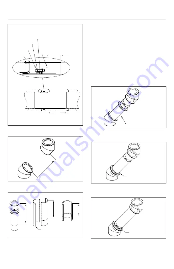
Figure 58
Figure 59
Figure 60
Figure 61
Figure 62
installation. See Figure 60.
d. Slide down the female coupling over the
male coupling of downstream part and fill
the gap between the female coupling and
the inner wall with S-2000 or S-650 sealant.
See Figure 61.
e. Slide down the retaining band to the
female coupling to mate heir flanges and
tighten the band. Then, install the locking
band over those flanges. See Figure 62.
f. Install the insulation over the inner wall
(DIS only). See Figure 63.
Figure 57
X Min
1" Min
Overlap
Insulation
Band (DIS
only)
Compression Band
Graphite Packing
Containing Ring
Telescopic
Outer Casing
Distance X
Cut to X + 1"
Cut 1 ¼ in the Bend to
Clear the Locking Band
Cut to X +
5/
8"
Cut to X
(DIS only)
Install Interior Assembly
Between Two Parts
Slide Down the Female
Coupling and Fill the Gap
With Sealant
Slide Down the Retaining
Band and Tighten the Band
and Install the Locking Band
Over the Flanges


