36
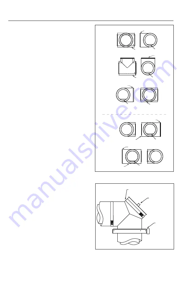
Figure 70
Figure 71
(TC). The location of the access port in the tee
is dependent on the orientation of the tee in
the final installation. Access port location is
coded as shown in Figure 70.
grEaSE tEE y (DIS onLy)
1. The Grease Tee Y (GTY) is very useful where
the grease duct must be accessed for clean-
out and inspection purposes. See Figure 71.
2. It can be used in place of the Grease Tee
90 (GT90) and provides excellent access
clearance for clean-outs.
3. Clean-outs must be located at all direction
changes in the grease ductwork.
4. Installation is the same as standard tee.
no tooL aCCESS Door - rEmoVaL For
InSpECtIon or CLEanIng
1. Unscrew the six (6) wing screws with your
hands and set them in a safe place during the
inspection (See Figure 72).
2. Remove the outer door from the outer wall
of the duct and set it in a safe place during
the inspection (See Figure 73).
3. Remove the insulation pad and set it in a
safe place during the inspection (See
Figure 73).
4. Unscrew the eight (8) wing screws and set
it in a safe place (See Figure 74).
5. Remove the Inner cover and set it in a safe
place (See Figure 74).
6. Inspect the ceramic gasket (white) and the
silicone gasket (gray) attached on the inside
of the Inner door for any damage (See Figure
75). If any damages, you must order one or
both gaskets.
replacement of the access door:
1. Replace the Inner door on the duct over
the access hole.
2. To make sure the door is well placed, put
back only the top and lower central wing
screw and tighten both.
3. Make sure that the door is well placed.
4. Put back the other six (6) wing screws and
tighten adequately.
Male Coupling
Grease dam
Position #1
Grease Tee
Position #1
Male Coupling
Grease dam
Position #2
Grease Tee
Position #2
Grease Tee
Position #3
Grease dam
Position #3
Standard Tee With
Dam Position #1
Grease dam
Male Coupling
Grease dam
Standard Tee With
Dam Position #2
Grease Tee Y
Tee Cap
Support


