31
NOTE: DIAGRAMS & ILLUSTRATIONS ARE NOT TO SCALE.
ANSI FLANGE ADAPTOR (FA)
The Flange Adaptor
FA
is intended for use as a connection to a class 125 or 150 ANSI
pipe flange. This type of connection requires a flange gasket and bolt set supplied by
the installer. The gasket and bolts are typically sold by pipe, valve and fittings houses
as an “
NBG
” (Nut, Bolt Gasket Kit) set.
An additional Outer Band
(BSE)
(for Model DAS PRO/DIS PRO) with insulation (for Models
DIS PRO
) is included for acting as the outer wall.
INSTALLATION:
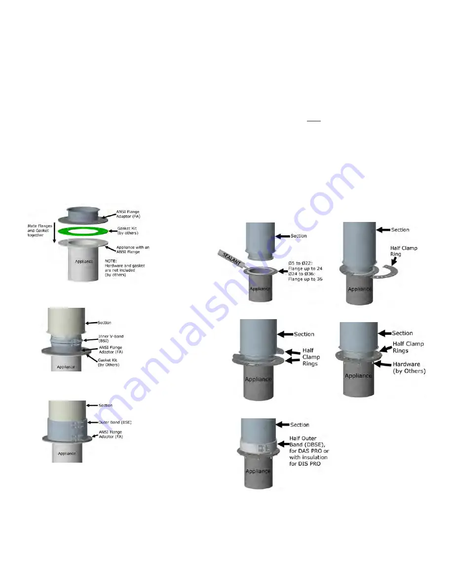
1. Place the Gasket kit (by others) on the appliance’s flange.
2. Mate all together the
FA
, the gasket and the Appliance’s flange.
3. Place and tighten all the bolt and nuts kit (by others) in every hole of the ANSI Flange,
4. Do Step 1 to 4 of
JOINT ASSEMBLY
Section to install a section on the 1/2 flange
side of the
FA
with the inner V-Band
(BSI)
.
For DIS PRO only:
5. Add insulation around the
FA
.
For DIS PRO and DAS PRO:
6. Add the Outer Band
(BSE)
around the
FA
, acting as an outer wall.
Step 1
Step 2
Step 4
Step 5
Step 6-7
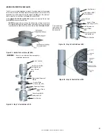
Figure 79 - Installation on a Flange with bolt pattern
Step 1-2
Step 3-4
Step 5-6
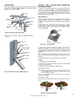
Figure 78 - Installation of an ANSI Flange ADAPTOR (FA)
HALF UNIVERSAL FLANGE (HUF)
The Half Universal Flange
(HUF)
is designed to connect Models
DCL / DAS PRO / DIS
PRO
pipe to a boiler or other appliance having a flanged outlet with a 4, 6, 8, 12, 16,
24 or no bolt pattern at all.
The HUF is a four flat 1/8” thick steel clamp rings supplied in two half-circle pieces
with 24 slots Ø3/8” x1” (for Ø5 to Ø24) and 36 slots (for Ø26 to Ø36), equally spaced
around the face of the adapter. No hardware included.
See
Figure 79
for installation on a bolt pattern flange. See
Figure 80
for an installation
on an appliance that have a flange without holes.
INSTALLATION ON A FLANGE
WITH
BOLT PATTERN:
1. Apply a continuous bead of sealant to the face of the pipe flange and to the appliance
flange.
2. Mate the pipe flange with the appliance
3. Position two half clamp rings over the pipe’s inner wall flange to form a complete
clamp ring, aligning the bolt slots in the HUF with bolt holes in the appliance.
4. If needed to have a 1/4” thick flange, add the two other half clamp rings
5. Secure clamp rings with bolts. Hardware are not included (by others)
6. For DIS PRO only, add insulation to fill the gap of the section.
7. For DIS PRO and DAS PRO only, add the Outer Band
(BSE)
.


