background image

6

TPM 083/12

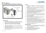
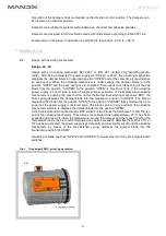
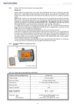
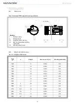
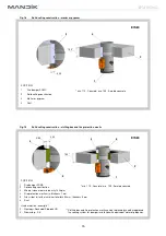
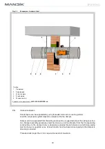
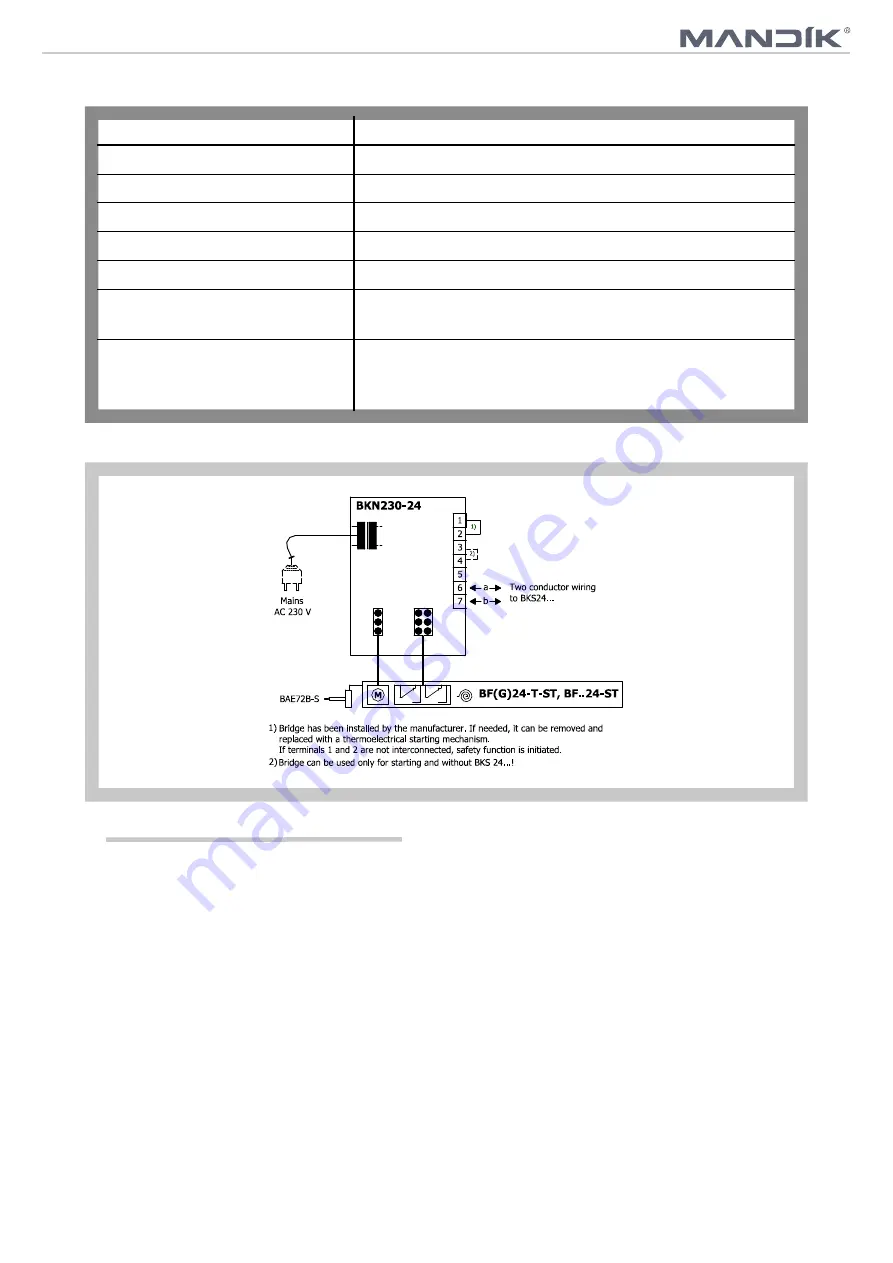
Fig. 6  Communication and Supply Device

 BKN 230-24

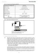
Tab. 2.3.2.  Communication and Supply Device BKN 230-24

2

Communication and Supply Device

BKN 230-24

Nominal voltage

AC 230V 50/60Hz

Power consumption

3,5 W (operating position)

Dimensioning

11 VA (including actuating mechanism)

Protection Class

II

Degree of protection

IP 42

Ambient Temperature

Storage Temperature

- 30 °C … + 50 °C

- 40 °C … + 50 °C

Connection - mains


- drive


- terminal board

Cable 0,9 m with EURO plug of 26 type

6 pole plug, 3 pole plug

screw terminals for conductor 2x1,5 mm

3.1. 

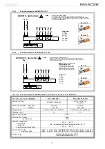
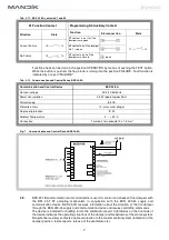
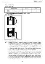
BKS 24-9A communication and control device is used for group control and checks of 1 to 9 fire 

dampers  with  the  actuating  mechanism  BFL  24-T-ST  in  connection  with  the  supply  and 

communication  device  BKN  230-24.  Signalisation  of  the  damper  position  is  individual;  the 

dampers  can  be  controlled  and tested only as a  group.  BKS  24-9A  is  intended  for  use  in  the 

distribution board and displays the operation situations and failure reports of the connected fire 

dampers. It is possible to signalise functions such as the damper position and failure reports or to 

transmit  them  further  to  the  system  by  means  of  integrated  auxiliary  switches.  BKS  24-9A 

receives  signals  from  BKN  230-24  through  the  two-conductor  wiring  and  issues  control 

commands. Proper damper operation is indicated by two light LED diodes:


Control ON = position OPERATION


Control OFF = position FAILURE


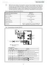
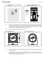
If the fire dampers do not reach the given position in time tolerable for displacing, the appropriate 

light diode FAILURE starts to flash and K1 contact is opened (current failure). In case that the 

faulty damper finally reaches its given position, K1 is closed and the failure report lights up shines 

(the failure is saved in memory).


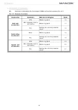
K2 - the auxiliary contact - is used for signalisation of the flap position to the master device. Function


of this auxiliary contact can be programmed through the terminal 14 according to the Tab. 3.1.1.

3. Communication and control devices

Summary of Contents for FDMC

Page 1: ......

Page 2: ...G 24 11 Material 24 VI INSPECTION TESTING 24 12 Inspection testing 24 VI TRANSPORTATION AND STORAGE 24 13 Logistic terms 24 VII ASSEMBLY ATTENDANCE MAINTENANCE AND REVISIONS 24 14 Assembly 24 15 Entry...

Page 3: ...an be set into the most advantageous position with respect to the operation and manipulation with the control device Fig 1 Fire damper FDMC 1 2 Damper characteristics CE certified acc to EN 15650 Test...

Page 4: ...maximum 140s If the actuating power supply is cut off due to loss of supply voltage activation of thermoelectrical actuating mechanism or pushing the reset button on the thermoelectrical starting mec...

Page 5: ...tion and power supply units Application examples for integration into monitoring and control systems or into bus networks can be found in the documentation of the connected communication and power sup...

Page 6: ...30V mains 2 conductor wiring is connected to BKN 230 24 by means of terminals 6 and 7 If the drive is supposed to be controlled without any signal from the central it can be switched on by means of a...

Page 7: ...or use in the distribution board and displays the operation situations and failure reports of the connected fire dampers It is possible to signalise functions such as the damper position and failure r...

Page 8: ...lure reports release of the ventilators etc Tab 3 1 1 BKS 24 9A contacts K1 and K2 K1 Function Contact Situation State Current Failure 15 16 No Failure 15 16 Programming K2 Auxiliary Contact Function...

Page 9: ...n insulation transformer AC 24 V damper position breakdown Notice Relay contacts are drawn without power 11 b a 2 conductor wiring to BKN230 24 Control on off Reset Test External buton optional be int...

Page 10: ...effective area Tab 4 2 1 Weight and effective area Size D a Weight Effective area Sef m Actuating mechanism 100 3 1 0 0036 BFL 125 3 4 0 0068 BFL 140 3 6 0 0092 BFL 150 3 7 0 0109 BFL 160 3 8 0 0129...

Page 11: ...all the installation space volume installation gap To provide needed access space to the control device all other objects must be situated at least 350 mm from the control parts of the damper Inspect...

Page 12: ...ampers has to be closed during installation process The damper body should not be deformed in the course of bricking in Once the damper is built in its blade should not grind on the damper body during...

Page 13: ...box Figure Solid wall construction Wet Mortar or gypsum 15 Wet installation next to wall ceiling Mortar or gypsum 17 Dry Stuffing box and fire protection mastic 16 Solid ceiling construction Mokr Mort...

Page 14: ...on 3 Mineral stone wool min density 140 kg m 4 Fire protection mastic min thickness 1 mm 5 Glass fiber felt with aluminium foil width 50 mm thickness 5 mm 6 Duct 3 Used materials example 3 Promapyr Ro...

Page 15: ...40 kg m3 A A 2 1 3 D 20 3 10 to 50 10 to 50 D 100 1 2 2 1 3 D 20 100 B B 2 2 B B 10 to 50 10 to 50 D 100 1 2 2 1 2 1 EIS 60 Notice Gap between damper and construction is filled by mortar or gypsum and...

Page 16: ...ck HD 3 Promastop P K 3 Fig 19 Solid ceiling construction stuffing box and fire protection mastic Fig 18 Solid ceiling construction mortar or gypsum POSITION 1 Fire damper FDMC 2 Solid ceiling constru...

Page 17: ...um wall construction mortar or gypsum 4 5 40 100 2 3 POSITION 1 Fire damper FDMC 2 Gypsum plate 3 Fire resistant insulation 4 Mortar or gypsum 5 Duct 1 Stuffing box and fire protection mastic can be r...

Page 18: ...einforced by profile UW CW Profil is fixed by screws 3 5 mm with corresponding length Distance between screws 200 mm Installation opening has to be reinforced by profile UW CW Profil is fixed by screw...

Page 19: ...M8 M20 2 Nut 3 Washer 4 Coupling Nut 5 Anchor 6 Hinge plate min thickness 10 mm 80 7 2 Horizontal installation Fire dampers can be suspended by using threaded rods and a mounting profiles Load the sus...

Page 20: ...ion system depend on weight of the fire damper Damper can be suspended from the ceiling construction or supported above the ceiling construc tion Damper assembly procedures must be done so as all load...

Page 21: ...ced under the ceiling construction Notice Damper must be firmly connected with extension piece by screws or rivets Suspension ring and mounting rail connected by bolt Suspension ring and mounting rail...

Page 22: ...Pressure loss calculation III TECHNICAL DATA p w 2 2 p Pa presure loss w m s air flow speed in nominal damper section kg m air density coefficient of local pressure loss for the nominal damper section...

Page 23: ...7 3 68 7 69 9 9 45 4 50 7 53 9 56 1 59 3 61 5 63 3 66 4 68 6 70 4 71 8 73 0 10 48 1 53 5 56 6 58 9 62 0 64 3 66 0 69 1 71 4 73 1 74 5 75 7 11 50 6 56 0 59 1 61 4 64 5 66 7 68 5 71 6 73 9 75 6 77 0 78...

Page 24: ...t LW1 10 log Sef Lrel 48 8 10 log 0 0374 11 5 23 1 dB 3 3 2 1 3 2 1 Tab 10 3 3 Relative level expressing the shape of the spectrum Lrel f Hz w m s 63 125 250 500 1000 2000 4000 8000 2 4 5 6 9 10 9 16...

Page 25: ...ient temperature must not exceed 40 C Dampers must be protected against mechanic damages when transported and manipulated During transportation the damper blade must be in the CLOSED position 13 2 Dam...

Page 26: ...back into the OPEN position can be done after restoration of power supply e g By releasing the RESET button or restoration of supply from ELECTRICAL FIRE SIGNALISATION VIII DATA OF THE PRODUCT 16 Data...

Page 27: ...60 communication and supply device BKN 230 24 has to be placed near the damper It is necessary for easy connection of actuating system equipped by BKN 230 24 device technical specifications design acc...

Page 28: ...r vo na zm ny v robku Aktu ln informace o v robku jsou uvedeny na www mandik cz MAND K a s Dob sk 550 26724 Hostomice esk republika Tel 420 311 706 706 Fax 420 311 584 810 311 584 382 E Mail mandik ma...

Reviews: