30
TPM 092/13
15.4.
Manual operation
Without power supply, the damper can be operated manually and fixed in any required position.
Release of the locking mechanism can be achieved manually or automatically by applying the
supply voltage.
15.5.
It is recommended to provide periodical checks, maintenance and service actions on Fire
Equipment by Authorized persons schooled by Producer.
15.6.
All effective safety standards and directives must be observed during fire damper assembly.
15.3.
Before entering the dampers with actuating mechanism into operation after their assembly and
by sequential checks, checks according 13. and following checks must be carried out.
Check of blade displacement into the breakdown position "CLOSED" can be done after cutting
off the actuating mechanism supply (e.g. by pressing the RESET button at the thermoelectrical
starting mechanism BAE 72B-S or cutting off the supply from ELECTRICAL FIRE
SIGNALISATION). Check of blade displacement back into the "OPEN" position can be done after
restoration of power supply (e.g. By releasing the RESET button or restoration of supply from
ELECTRICAL FIRE SIGNALISATION).
15.2.
Before entering the dampers with manual control (design .01v1 and .01v2 into operation after
their assembly and by sequential checks, checks according 15.1. and following checks must be
carried out.
Check of thermal protective fuse and closing mechanism.
Push initiation lever lock "OPEN" to release the control lever and check its displacement into the
position "CLOSED". Closing must be smart and the control lever must be firmly locked with a lever
lock "CLOSED". In case that the closing is not smart enough and the control lever is not locked
with the ever lock in the position"CLOSED", higher pre-stretch of the closing spring must be set
by using new hole in base plate or using new spring.
Proper function of the thermal fuse can be checked when the fuse is removed from the starting
mechanism. The initiation lever must be turned over and control lever is moved to position
"CLOSED". If this is not possible, then the starting mechanism spring must be checked or the
base plate must be replaced. The base plate is attached to the damper body with four M5 screws.
Displacing the damper blade into "OPEN" position is done the following way:
Push lever lock "CLOSED" and move control lever from "CLOSED" position towards position
"OPEN" until control lever is locked in lever lock "OPEN".
VIII. DATA OF THE PRODUCT
16. Data label
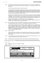
16.1.
Data label is placed on the casing of fire damper.
Fig. 45 Data label
Certificate:
WEIGHT (kg):
Dobříšská 550
267 24 Hostomice
MANDÍK, a.s.
Czech Republic
FIRE DAMPER FDMD
DESIGN:
SERIAL NUMBER:
SIZE:
1391
1391-CPR-0089/2014
14
EN 15650:2010
CLASSIFICATION:
EI 90 (ve ho i o) S
TPM092/13

