13
2
1
N L1
S3
S2
S1
S6
S5
S4
For separation from the mains, a device that
insulates polar conductors must be at disposal
(Minimum distance between contacts 3 mm).
<5°
<80°
BAE72BS
Tf1
Tf2
Tf3
LED
Parrallel connection of other driver is possible.
Pay attention to the power input data.
12. Before entering the dampers into operation after assembly and after sequential revisions, checks and
functionality tests of all designs including operation of the electrical components must be done. After
entering into operation, these revisions must be done according to requirement set by national
regulations.
9.
All fire dampers has to be closed during installation process. The damper body should not be deformed
in the course of bricking in. Once the damper is built in, its blade should not grind on the damper body
during opening or closing.
10. To provide needed access space to the control device, all other objects must be situated at least
350 mm from the control parts of the damper. Inspection hole must be accessible.
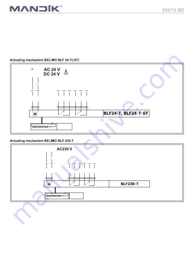
11. Electrical components, wiring diagrams.
~
1
2
+
S2
S1
S3
S5
S4
S6
an insulation transformer.
Parrallel connection of other driver is possible.
BLF24STT: Design with connector plugs for communication
to network and communication device BKN23024
Connection through
Pay attention to the power input data.
<5°
<80°
BAE72BS
Tf1
Tf2
Tf3
LED
Visual inspection of proper damper integration, inside damper area, damper blade, contact surfaces and
silicon sealing.
13. Before entering the dampers into operation after their assembly and by sequential checks, the following
checks must be carried out.
Inspection hole disassembly: release the covering lid by removing the two screws in the corners of
inspection hole. Then remove lid from its original position.


