MANDÍK, a. s. • Dobříšská 550 • 267 24 Hostomice • Česká republika • Tel.: +420 311 706 742 • E-Mail: mandik@mandik.cz
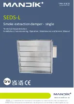
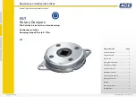
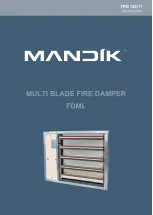
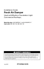
FDML
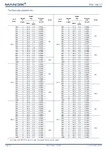
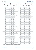
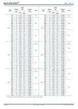
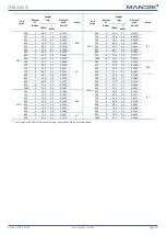
Multi blade fire damper
Technical Documentation
Installation, Commissioning, Operation, Maintenance and Service Manual
TPM 130/17
Version 2023-10-31