


2
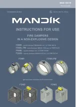
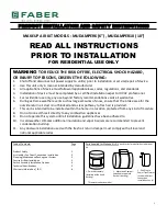
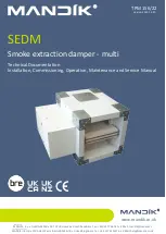
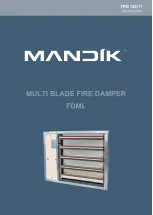
FDML multi blade fire dampers are in motor-driven versions with servo drives and they have the following two main applications:
■
They are applied as fire closures without following air condition duct with cover grids for closure of vents in fire dividingwalls,
constructions, elevator and other shafts, cable and other channels preventing spread of fire heat and other combustion
products.
■
If applied as multi blade fire damper with air condition connecting pipes from both ends (without grids) or with connecting
pipe at one end (1x grid) they prevent spreading of heat and combustion products through such piping system.
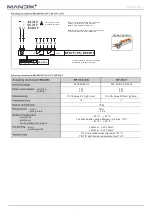
If the damper is hit with fire it will automatically (or remotely as the case may be) be closed and spread of fire from one fire
sector to another will be prevented. Damper blades automatically close air flow using servo check spring. The servo check
spring is put into operation at activation of thermo-electric actuator by pressing reset button or with interruption of servo
feeding. Once the blades have been closed the damper is sealed using rubber seal against fume penetration. At the same
time damper blade is placed in a material which increases its volume by actuating higher temperature and seals the damper
hermetically. Dampers are not furnished with inspection chambers. If these dampers are used as dampers for simple
maintenance and revision they must be completed with connecting inspection equipment installed just behind the damper.
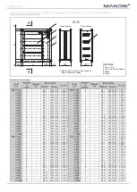
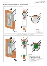
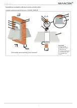
Plaster / Mortar
Rigid wall structure, min. thickness 100 mm
EI 90 S, E 120 S
Mineral wool (density min.140kg/m
³
) furnished
with fire stop SEALANT (min. thickness 1 mm)
(i.e. HILTI Acrylic sealant CFS-S ACR) and fire
stop COATING, min., thickness 1 mm
(for instance HILTI Firestop coating CFS-CT).
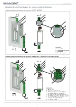
Rigid wall or plasterboard structure, min.
thickness 100 mm
EI 90 S, E 120 S
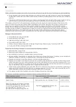
■
CE certification according to EN 15650
■
Tested according to EN 1366-2
■
Classified according to EN 13501-3+A1
■
Fire resistance EI 90 S, E 120 S
■
Damper casing air leakage category B, air leakage through damper blade category 3 according to EN 1751
■
Cycling tests C10000 according to EN 15650
■
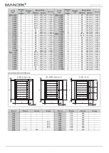
Maximum airflow velocity 12m/s.
■
Maximum pressure difference on damper blade 1500 Pa.
■
Even distribution of air flow in complete damper cross section area.
■
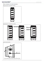
Damper operating characteristics are independent on airflow direction through the damper. The damper can be installed with
blade axis vertically or horizontally, temperature sensor must always be in damper upper part.
■
Dampers are intended for airs without abrasive, chemical and sticky admixtures.
■
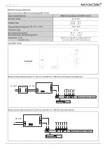
Dampers are intended for environments protected from weathering with classification of climatic conditions category 3K5,
without condensing, icing, ice coating, water also from other sources different from rain and with temperature limits - 10 to
+50°C according to EN 60 721-3-3 amend..A2. When the damper is furnished with electrical elements the temperature
scope is reduced according to temperature limits of applied electrical elements.
■
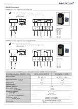
Optical smoke detector MHG 231 with socket MHY 734.031 is intended for environments protected from weathering of
categories 3K5/3Z1/3Z8/3B1/3C2/3S1/3M2 within temperature scope -25°C to +70°C, max. relative humidity 95% at 40°C,
without condensing, icing and ice formation according to EN 60 721-3-3 amend.A2.
■
If the damper is used for self-ventilation it must be furnished with grids from both sides.
Summary of Contents for FDML
Page 1: ......