background image

3

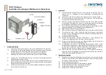
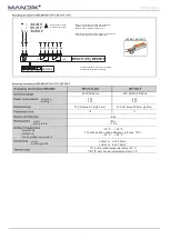
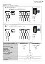
Servo drives with different torque strengths are used according to damper size. Two different servo finished products can be used,
Belimo and Gruner. When Belimo actuators are used they are marked: (230V) BFL, BFN, BF 230-T or (24V) BFL, BFN, BF 24-T
(hereinafter  "servo")  and  when  Gruner  products  are  used  their  marking  is  (230V)  340TA-230D-03-S2/8F12,  340TA-230-05-
S2/8F12, 360TA-230-12-S2/8F12, 360TA-230-20-S2/8F12 or (24V) 340TA-024D-03-S2/8F12, 340TA-024-05-S2/8F12, 360TA-
024-12-S2/8F12, 360TA-024-20-S2/8F12. Actuators feature reverse spring loaded movement by 90°and include thermo-electric
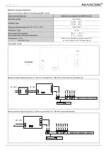
actuation devices reacting to tempe72°C. Having been connected to 24 V or to 23 V AC/DC power supply respectively
this device sets damper blade to working position OPEN and at the same time it switches over its own check spring. During the
time when servo is under voltage, damper blade is in the position OPEN and check spring is tensioned. Time for complete opening
of damper blade from CLOSED position to OPEN is max. 60s If servo powering is interrupted (by loss of supply voltage or by
pressing reset button on thermo-electric actuator BAT or when temperature e72°C), the check spring sets damper blade
to emergency position CLOSED. Time for complete changeover of damper blade from OPEN position to CLOSED is max. 20 s.
If supply voltage is restored (the blade may be in any position) servo starts to set the blade again to the position OPEN. This new
opening of the damper does not occur spontaneously after restoration of supply voltage if fuses Tf1 and Tf2 have been activated
(Tf1 with exceeding temperature in damper environment, Tf2 with exceeding of temperature inside air condition duct).

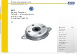
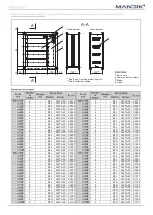
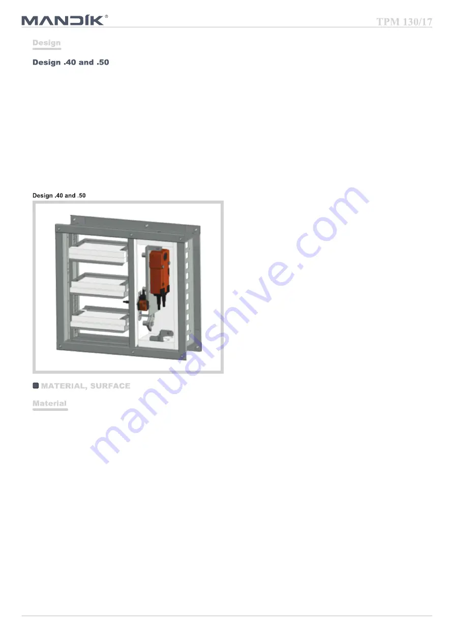
Damper frame is made from galvanized sheet metal.
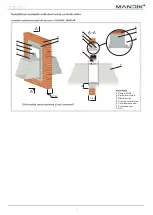
Covering protection grills (similar to type KMM) are produced from sheet iron and coated with baking varnish in colour RAL 9010.
Requirements for other colours must be discussed with manufacturer in advance.
Damper blades are made from asbestos-free fire protective plates from mineral fibres.
Closing mechanism is zinc-coated. Coupling elements are zinc-coated.

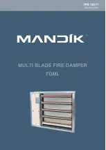
Summary of Contents for FDML

Page 1: ......

Page 2: ...ng for design manufacture delivery storage assembly operation maintenance and serviceability checks Description 2 Design 3 Material 3 Dimensions and weight 4 Electrical components wiring diagram 8 Installation and placement 13 Checks 18 Tests 18 Logistic data 18 Guarantee 18 Assembly 18 Putting into operation and serviceability checks 18 Spare parts 18 Nameplate 19 ...

Page 3: ...re stop SEALANT min thickness 1 mm i e HILTI Acrylic sealant CFS S ACR and fire stop COATING min thickness 1 mm for instance HILTI Firestop coating CFS CT Rigid wall or plasterboard structure min thickness 100 mm EI 90 S E 120 S CE certification according to EN 15650 Tested according to EN 1366 2 Classified according to EN 13501 3 A1 Fire resistance EI 90 S E 120 S Damper casing air leakage catego...

Page 4: ...opening of damper blade from CLOSED position to OPEN is max 60s If servo powering is interrupted by loss of supply voltage or by pressing reset button on thermo electric actuator BAT or when temperature exceeds 72 C the check spring sets damper blade to emergency position CLOSED Time for complete changeover of damper blade from OPEN position to CLOSED is max 20 s If supply voltage is restored the ...

Page 5: ...340TA 05 0 1606 2 BFL 340TA 03 0 0360 2 BFL 340TA 03 0 0444 2 BFL 340TA 03 0 0370 2 BFL 340TA 03 0 0457 3 BFL 340TA 03 0 0456 3 BFL 340TA 03 0 0562 3 BFL 340TA 03 0 0552 3 BFL 340TA 03 0 0681 4 BFL 340TA 03 0 0574 4 BFL 340TA 03 0 0708 4 BFL 340TA 03 0 0681 4 BFL 340TA 03 0 0840 4 BFL 340TA 03 0 0723 4 BFL 340TA 03 0 0892 5 BFL 340TA 03 0 0809 5 BFL 340TA 03 0 0998 5 BFL 340TA 03 0 0873 5 BFL 340T...

Page 6: ... 340TA 05 0 1429 3 BFN 340TA 05 0 1116 6 BFN 340TA 05 0 1557 3 BFN 340TA 05 0 1352 6 BFN 340TA 05 0 1621 4 BFN 340TA 05 0 1404 7 BFN 340TA 05 0 1748 4 BFN 340TA 05 0 1666 7 BFN 340TA 05 0 1908 4 BFN 340TA 05 0 1771 8 BFN 360TA 12 0 1940 5 BFN 360TA 12 0 1981 8 BFN 360TA 12 0 2099 5 BFN 360TA 12 0 2138 2 BFL 340TA 03 0 0612 5 BFN 360TA 12 0 2243 2 BFL 340TA 03 0 0630 6 BFN 360TA 12 0 2295 3 BFL 340...

Page 7: ...6 BF 360TA 12 0 2751 3 BFN 340TA 05 0 1627 6 BF 360TA 12 0 2996 3 BFN 340TA 05 0 1971 6 BF 360TA 12 0 3119 4 BFN 360TA 12 0 2048 7 BF 360TA 12 0 3365 4 BFN 360TA 12 0 2430 7 BF 360TA 12 0 3672 4 BFN 360TA 12 0 2582 8 BF 360TA 12 0 3733 5 BF 360TA 12 0 2888 8 BF 360TA 12 0 4040 5 BF 360TA 12 0 3117 2 BFL 340TA 03 0 1116 5 BF 360TA 12 0 3270 2 BFL 340TA 03 0 1149 6 BF 360TA 12 0 3346 3 BFN 340TA 05 ...

Page 8: ...0TA 12 0 2584 7 BF 360TA 12 0 4735 4 BF 360TA 12 0 3066 7 BF 360TA 12 0 5167 4 BF 360TA 12 0 3258 8 BF 360TA 20 0 5253 5 BF 360TA 12 0 3644 8 BF 360TA 20 0 5685 5 BF 360TA 12 0 3933 2 BFN 340TA 05 0 1536 5 BF 360TA 12 0 4126 2 BFN 340TA 05 0 1581 6 BF 360TA 12 0 4222 3 BFN 360TA 12 0 1947 6 BF 360TA 12 0 4319 3 BFN 360TA 12 0 2358 6 BF 360TA 12 0 4704 4 BFN 360TA 12 0 2450 6 BF 360TA 12 0 4897 4 B...

Page 9: ...tage not permitted at the both auxiliary switches Application examples for integration into monitoring and control systems or into bus networks can be found in the documentation of the connected communication and power supply unit 1 blue 2 brown S1 violet S2 red S3 white S4 orange S5 pink S6 grey AC 230 V 50 60 Hz AC 24 V 50 60 Hz DC 24 V motoring holding 3 5 5 W 1 1 2 1 W 2 5 4 W 0 8 1 4 W 6 5 10...

Page 10: ...mum distance between contacts 3 mm to network and communication device BKN230 24 BAE72B S Tf1 Tf2 Tf3 LED 230V 50 60 Hz 24V AC DC 50 60 Hz motoring holding 7 W 2 W 8 W 3 W 10 VA Imax 8 3 A 5 ms 12 5 VA Imax 500 mA 5 ms III II IP 54 motor spring return 140 s 16 s normal duty safety duty non operating temperature 20 C 50 C The safe position will be attained up to max 75 C 40 C 50 C motor auxiliary s...

Page 11: ...ite WH4 white WH5 white WH6 white Attention Mains voltage Servo must be protected by breaker max 16 A Parallel connection of other servo drives is possible Respect power input data Combination of mains voltage and use of signals from limit switches by very low voltage is not allowed 1 2 TA 72 TF1 TF2 LED test 80 5 1 2 3 4 5 6 S1 S2 WH WH WH WH WH WH BU BN Connect through separating transformer Par...

Page 12: ... 11 5 VA 7 VA II III IP 54 motor spring return 75 s 20 s normal duty safety duty non operating temperature 30 C 50 C 75 C 30 C 50 C motor auxiliary switch cable 1 m 2 x 0 75 mm cable 1 m 6 x 0 75 mm TF1 temperature inside Duct 72 C TF2 temperature outside Duct 71 C 230V 50 60 Hz 24V AC DC 50 60 Hz motoring holding 10 5 W 2 5 W 10 5 W 2 5 W 22 5 VA 14 VA II III IP 54 motor spring return 75 s 20 s n...

Page 13: ...18 28 V DC 24 30 V without servo drive max 50mA IP 30 25 C 70 C 5 C 40 C mains drive BF Top cable 1m connected to terminal board XT1 screw terminals in XT2 terminal board AC 24V AC 230V L1 N ZNP 10 24V 230V 24V AC 24V ...

Page 14: ...ansfer of load effects from any walls structures and other parts onto damper frame are excluded completely During walling in the damper frame must not be deformed After having been built in the damper its blades must not rub on damper frame or one another When dampers are installed in walls they must be built in in such a way so that the damper side with thermo electric actuator mates with the wal...

Page 15: ...A A A A 100 100 50 Damper FDML Rigid wall structure Mineral wool with min density 140kg m for instance Rockwool Steprock HD Fire stop SEALANT min thickness 1 mm for instance HILTI Acrylic sealant CFS S ACR Fire stop COATING min thickness 1 mm HILTI Firestop coating CFS CT Fire stop cover plates ...

Page 16: ...for instance Rockwool Steprock HD Fire stop SEALANT min thickness 1 mm for instance HILTI Acrylic sealant CFS S ACR Fire stop COATING min thickness 1 mm HILTI Firestop coating CFS CT Fire stop cover plates A A A A 100 100 Damper FDML Plasterboard wall structure Plaster mortar Fire stop cover plates 50 ...

Page 17: ...16 Damper FDML Rigid wall structure Plaster mortar Fire stop cover plates Covered mechanism Covered sensor Duct 100 100 A A A A 50 ...

Page 18: ...17 150 150 150 150 Frame into the wall Duct Covering grill Before walling in the damper casing must be grounded Earth connection screw ...

Page 19: ...al qualification with validity 5 years and its prolongation must be provided by AUTHORIZED PERSON itself directly at trainer premises When terminates validity of the CERTIFICATE such CERTIFICATE becomes void and it is discarded from trainer files Only qualified persons can be trained who then answer for performed works Damper must be installed with respecting of all safety standards and regulation...

Page 20: ...V AC DC with thermo electric actuator 50 with servo drive Belimo or Gruner 24V AC DC with optical smoke detector MHG 231 assembly voltage 24V AC 51 Optical smoke detectors MHG 231 and supply unit BKN 230 24 MP are in bulk 2 grills included damper is inside wall protected from both sites with grills there is no connection with air ductwork without grills damper is part and connected to the air duct...

Reviews: