8
2,2
2,6
3,2
3,6
4
4,5
5,1
5,8
–
6,7
7,7
9
10,4
12
14,1
16,7
–
3,3
3,7
4,3
4,7
5,1
5,6
6,2
6,9
–
7,8
8,8
10,1
11,5
13,4
15,5
18,1
–
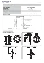
BFL24-T(-ST), BFL230-T
100, 125, 160, 180, 200, 225, 250, 280, 315, 355, 400, 450
BFN24-T(-ST), BFN230-T
500, 560, 630
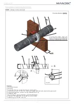
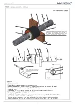
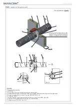
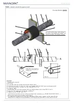
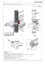
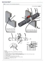
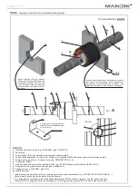
Fire dampers are suitable for installation in arbitrary position in vertical and horizontal passages of fire separating constructions.
Damper assembly procedures must be done so as all load transfer from the fire separating constructions to the damper body is
absolutely excluded. Back-to-back air-ducting must be hung or supported so as all load transfer from the back-to-back piping to
the damper is absolutely excluded. Installation gap must be filled by approved material perfectly in all the installation space volume
(installation gap). To be able to provide inspection, inside of the fire damper is the damper with camera inspection hole standardly
equipped. For other service works, the external access door (inspection hole) must be installed on the air duct, next to the fire
damper.
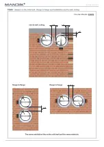
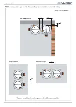
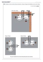
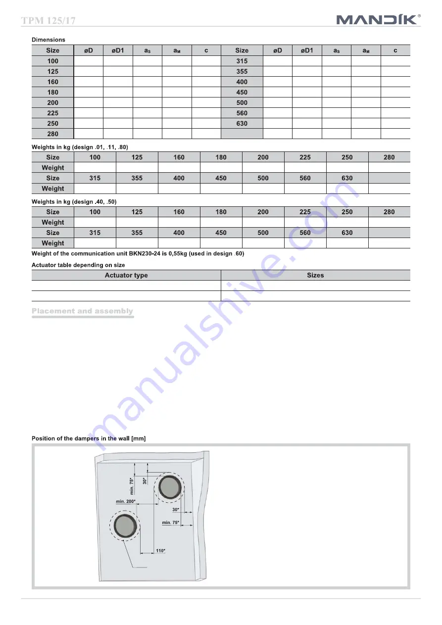
The distance between the fire damper and the construction (wall, ceiling) must be minimum 75 mm. In case that two or more
dampers are supposed to be installed in one fire separating construction, the distance between the adjacent dampers must be at
least 200 mm according to EN 1366-2 paragraph 13.6.
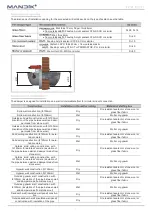
The control mechanism has to be protected (covered) against damage and pollution during installation process. All fire dampers
has to be closed during installation process. The damper body should not be deformed in the course of bricking in. Once the
damper is built in, its blade should not grind on the damper body during opening or closing.
98
190
–
–
–
313
405
–
12
70
123
215
–
–
–
353
445
2
32
90
158
250
–
–
–
398
490
24,5
54,5
112,5
178
270
–
–
2,5
448
540
49,5
79,5
137,5
198
290
–
–
12,5
498
590
74,5
104,5
162,5
223
315
–
–
25
558
650
104,5
134,5
192,5
248
340
–
–
37,5
628
720
139,5
169,5
227,5
278
370
–
–
52,5
–
–
–
–
–
–
Collar
* Other values - see the installation details for installation
flange to flange and next to ceiling or/and wall.
Summary of Contents for FDMS Series
Page 1: ......
Page 12: ...11 Fire classification 96 47 47 96 96...
Page 15: ...14 Fire classification 96 47 47 96 96...
Page 18: ...17 Fire classification 96 47 47 96 96...
Page 29: ...28...
Page 30: ...29...
Page 31: ...30...


