

Page 13
Version 2022-12-20
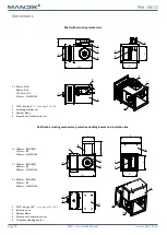
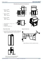
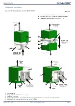
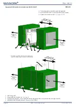
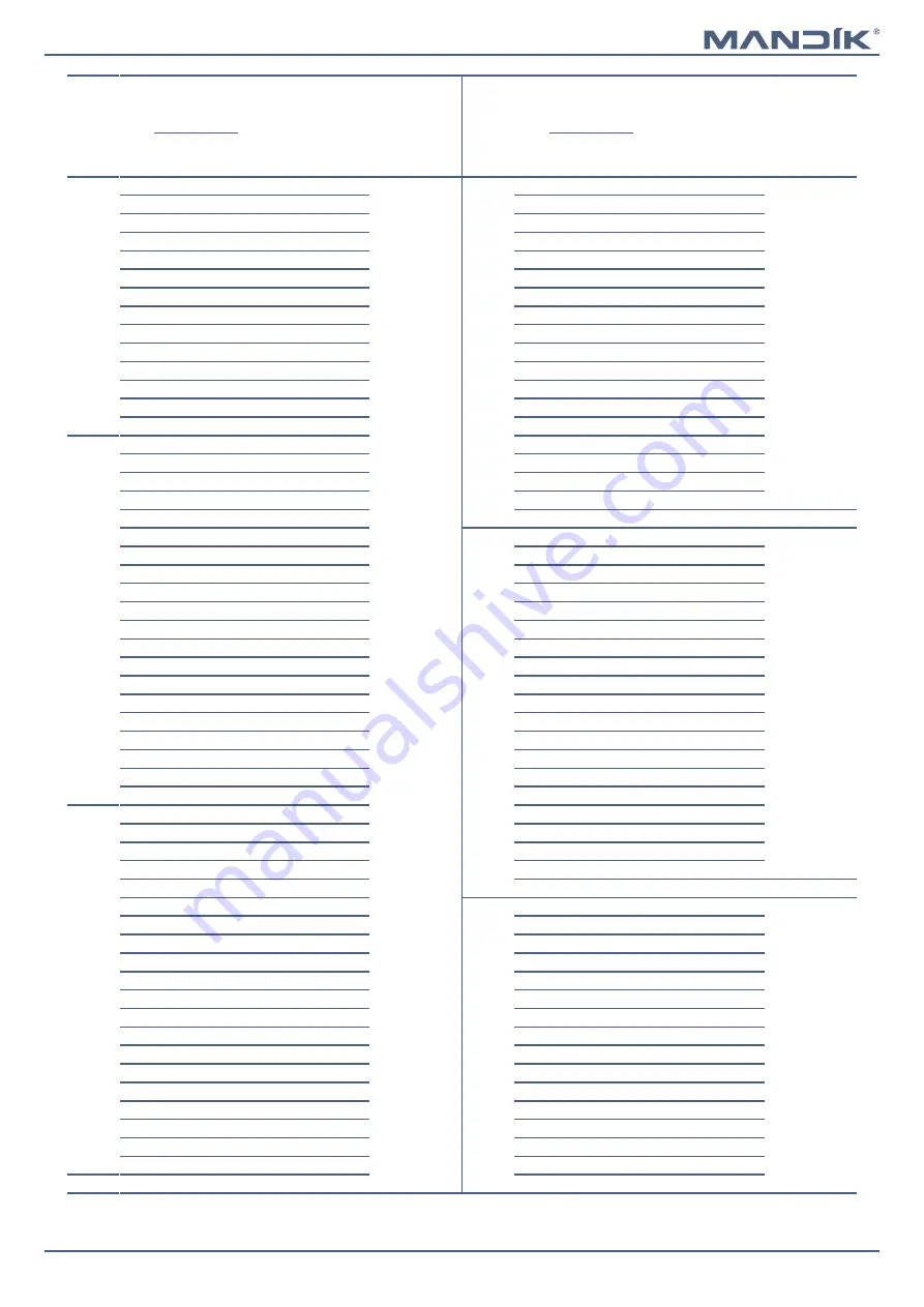
MSD - multi smoke damper
TPM 159/22
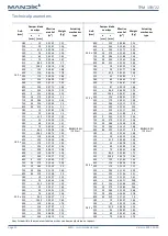
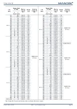
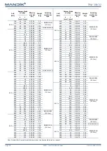
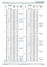
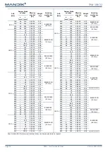
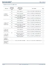
A x B
[mm]
Damper blade
overlaps
Effective
area Sef
[m
2
]
Weight
[kg]
Actuating
mechanism
type
A x B
[mm]
Damper blade
overlaps
Effective
area Sef
[m
2
]
Weight
[kg]
Actuating
mechanism
type
a
[mm]
c
[mm]
a
[mm]
c
[mm]
280 x
315
–
86,5
0,0655
17,8
BELIMO BEN
(15 N.m)
355 x
200
–
29
0,0449
16,3
BELIMO BEN
(15 N.m)
355
–
106,5
0,0761
18,9
225
–
41,5
0,0534
17
400
–
129
0,0880
20
250
–
54
0,0619
17,7
450
–
154
0,1012
21,3
280
–
69
0,0721
18,6
500
–
179
0,1145
22,6
300
–
79
0,0789
19,2
550
–
204
0,1277
23,8
315
–
86,5
0,0840
19,6
560
–
209
0,1304
24,1
355
–
106,5
0,0976
20,7
600
–
229
0,1410
25,1
400
–
129
0,1129
22
630
–
244
0,1489
25,9
450
–
154
0,1299
23,4
650
9
254
0,1542
26,4
500
–
179
0,1469
24,8
700
34
279
0,1675
27,7
550
–
204
0,1639
26,2
710
39
284
0,1701
27,9
560
–
209
0,1673
26,5
750
59
304
0,1807
28,9
600
–
229
0,1809
27,6
800
84
329
0,1940
30,2
630
–
244
0,1911
28,5
300 x
180
–
19
0,0319
14,7
650
9
254
0,1979
29
200
–
29
0,0376
15,3
700
34
279
0,2149
30,5
225
–
41,5
0,0447
15,9
710
39
284
0,2183
30,7
250
–
54
0,0519
16,6
750
59
304
0,2319
31,9
280
–
69
0,0604
17,4
800
84
329
0,2489
34,3
BELIMO BEE (25 N.m)
300
–
79
0,0661
17,9
400 x
180
–
19
0,0431
16,5
BELIMO BEN
(15 N.m)
315
–
86,5
0,0704
18,3
200
–
29
0,0508
17,2
355
–
106,5
0,0818
19,4
225
–
41,5
0,0604
17,9
400
–
129
0,0946
20,5
250
–
54
0,0701
18,7
450
–
154
0,1089
21,8
280
–
69
0,0816
19,6
500
–
179
0,1231
23,2
300
–
79
0,0893
20,2
550
–
204
0,1374
24,5
315
–
86,5
0,0951
20,6
560
–
209
0,1402
24,7
355
–
106,5
0,1105
21,8
600
–
229
0,1516
25,8
400
–
129
0,1278
23,2
630
–
244
0,1602
26,6
450
–
154
0,1471
24,7
650
9
254
0,1659
27,1
500
–
179
0,1663
26,2
700
34
279
0,1801
28,4
550
–
204
0,1856
27,6
710
39
284
0,1830
28,7
560
–
209
0,1894
27,9
750
59
304
0,1944
29,7
600
–
229
0,2048
29,1
800
84
329
0,2086
31
630
–
244
0,2164
30
315 x
180
–
19
0,0336
15
650
9
254
0,2241
30,6
200
–
29
0,0396
15,6
700
34
279
0,2433
32,1
225
–
41,5
0,0471
16,2
710
39
284
0,2472
32,4
250
–
54
0,0546
16,9
750
59
304
0,2626
33,6
280
–
69
0,0636
17,7
800
84
329
0,2818
36,1
BELIMO BEE (25 N.m)
300
–
79
0,0696
18,3
450 x
180
–
19
0,0487
17,5
BELIMO BEN
(15 N.m)
315
–
86,5
0,0741
18,7
200
–
29
0,0574
18,1
355
–
106,5
0,0861
19,7
225
–
41,5
0,0683
18,9
400
–
129
0,0996
20,9
250
–
54
0,0792
19,7
450
–
154
0,1146
22,3
280
–
69
0,0922
20,7
500
–
179
0,1296
23,6
300
–
79
0,1009
21,3
550
–
204
0,1446
24,9
315
–
86,5
0,1074
21,8
560
–
209
0,1476
25,2
355
–
106,5
0,1248
23,1
600
–
229
0,1596
26,3
400
–
129
0,1444
24,5
630
–
244
0,1686
27,1
450
–
154
0,1662
26,1
650
9
254
0,1746
27,6
500
–
179
0,1879
27,6
700
34
279
0,1896
29
550
–
204
0,2097
29,2
710
39
284
0,1926
29,2
560
–
209
0,2140
29,5
750
59
304
0,2046
30,3
600
–
229
0,2314
30,8
800
84
329
0,2196
31,6
630
–
244
0,2445
31,8
355 x 180
–
19
0,0381
15,7
650
9
254
0,2532
32,4
Sizes listed within the maximum/minimum sizes can be manufactured on request.