
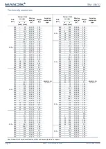
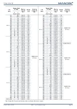
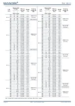
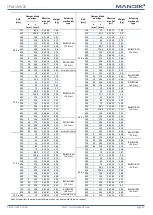

MSD - multi smoke damper
Page 16
Version 2022-12-20
TPM 159/22
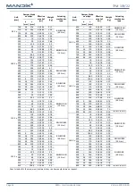
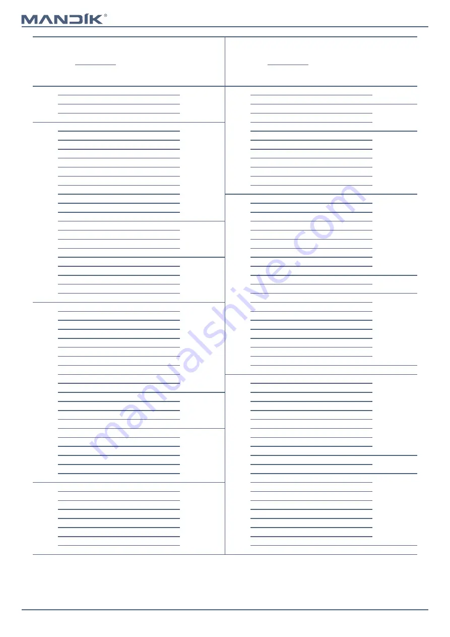
A x B
[mm]
Damper blade
overlaps
Effective
area Sef
[m
2
]
Weight
[kg]
Actuating
mechanism
type
A x B
[mm]
Damper blade
overlaps
Effective
area Sef
[m
2
]
Weight
[kg]
Actuating
mechanism
type
a
[mm]
c
[mm]
a
[mm]
c
[mm]
900 x
700
34
279
0,5593
51,7
BELIMO BE
(40 N.m)
1250 x
400
–
129
0,4100
45,7
BELIMO BEN
(15 N.m)
710
39
284
0,5682
52,2
450
–
154
0,4718
48,8
750
59
304
0,6036
54,1
500
–
179
0,5335
52,9
BELIMO BEE
(25 N.m)
800
84
329
0,6478
56,5
550
–
204
0,5953
55,9
1000 x
180
–
19
0,1103
27,4
BELIMO BEN
(15 N.m)
560
–
209
0,6076
56,5
200
–
29
0,1300
28,6
600
–
229
0,6570
59
BELIMO BE
(40 N.m)
225
–
41,5
0,1546
30
630
–
244
0,6941
60,8
250
–
54
0,1793
31,3
650
9
254
0,7188
62,1
280
–
69
0,2088
32,9
700
34
279
0,7805
65,1
300
–
79
0,2285
33,9
710
39
284
0,7929
65,8
315
–
86,5
0,2433
34,7
750
59
304
0,8423
68,2
355
–
106,5
0,2827
36,8
800
84
329
0,9040
71,3
400
–
129
0,3270
39,1
1400 x
180
–
19
0,1551
34,7
BELIMO BEN
(15 N.m)
450
–
154
0,3763
41,7
200
–
29
0,1828
36,2
500
–
179
0,4255
44,4
225
–
41,5
0,2174
38
550
–
204
0,4748
47
BELIMO BEE
(25 N.m)
250
–
54
0,2521
39,7
560
–
209
0,4846
48,5
280
–
69
0,2936
41,7
600
–
229
0,5240
50,6
300
–
79
0,3213
43
630
–
244
0,5536
52,2
315
–
86,5
0,3421
44
650
9
254
0,5733
53,2
BELIMO BE
(40 N.m)
355
–
106,5
0,3975
46,7
700
34
279
0,6225
55,9
400
–
129
0,4598
49,7
710
39
284
0,6324
56,4
450
–
154
0,5291
54
BELIMO BEE
(25 N.m)
750
59
304
0,6718
58,5
500
–
179
0,5983
57,4
800
84
329
0,7210
61,1
550
–
204
0,6676
60,7
BELIMO BE
(40 N.m)
1100 x
180
–
19
0,1215
29,2
BELIMO BEN
(15 N.m)
560
–
209
0,6814
61,4
200
–
29
0,1432
30,5
600
–
229
0,7368
64
225
–
41,5
0,1703
32
630
–
244
0,7784
66
250
–
54
0,1975
33,4
650
9
254
0,8061
67,4
280
–
69
0,2300
35,1
700
34
279
0,8753
70,7
300
–
79
0,2517
36,2
710
39
284
0,8892
71,4
315
–
86,5
0,2680
37
750
59
304
0,9446
74
355
–
106,5
0,3114
39,2
800
84
329
1,0138
84,2
SCHISCHEK InMax 50.75
400
–
129
0,3602
41,8
1500 x
180
–
19
0,1663
36,5
BELIMO BEN
(15 N.m)
450
–
154
0,4145
44,6
200
–
29
0,1960
38,1
500
–
179
0,4687
48,4
BELIMO BEE
(25 N.m)
225
–
41,5
0,2331
40
550
–
204
0,5230
51,2
250
–
54
0,2703
41,7
560
–
209
0,5338
51,7
280
–
69
0,3148
43,9
600
–
229
0,5772
54
300
–
79
0,3445
45,3
630
–
244
0,6098
55,7
BELIMO BE
(40 N.m)
315
–
86,5
0,3668
46,3
650
9
254
0,6315
56,8
355
–
106,5
0,4262
49,1
700
34
279
0,6857
59,6
400
–
129
0,4930
52,3
710
39
284
0,6966
60,1
450
–
154
0,5673
56,8
BELIMO BEE
(25 N.m)
750
59
304
0,7400
62,4
500
–
179
0,6415
60,3
800
84
329
0,7942
65,2
550
–
204
0,7158
63,9
BELIMO BE
(40 N.m)
1250 x
180
–
19
0,1383
31,9
BELIMO BEN
(15 N.m)
560
–
209
0,7306
64,6
200
–
29
0,1630
33,3
600
–
229
0,7900
67,4
225
–
41,5
0,1939
35
630
–
244
0,8346
69,5
250
–
54
0,2248
36,5
650
9
254
0,8643
70,9
280
–
69
0,2618
38,4
700
34
279
0,9385
74,4
300
–
79
0,2865
39,6
710
39
284
0,9534
75,1
315
–
86,5
0,3050
40,5
750
59
304
1,0128
77,9
355
–
106,5
0,3544
43
800
84
329
1,0870
88,3
SCHISCHEK InMax 50.75
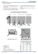
Sizes listed within the maximum/minimum sizes can be manufactured on request.