background image


M&S Systems |  800.421.1587 | www.mssystems.com


i

XDM

4600 

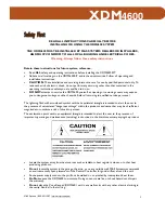
Safety First 

READ ALL INSTRUCTIONS CAREFULLY BEFORE 

INSTALLING OR USING THE XDM4600 SYSTEM 

THE XDM4600 MUST BE INSTALLED BY M&S SYSTEMS DEALERS OR INSTALLERS, 

AND MUST CONFORM TO ALL LOCAL BUILDING AND ELECTRICAL CODES. 

Warning: Always follow these safety instructions. 


Retain these instructions for future system reference. 


Read 

ALL

 safety and operating instructions before installing the XDM4600KIT. 


Adhere to all warnings on the XDM4600KIT and in these instructions. Follow all operating and 
installation instructions. 


CAUTION

: These installation and servicing instructions are for use by qualified personnel only. To 

reduce the risk of electric shock, do not perform any servicing other than that contained in the 

operating instructions unless you are qualified to do so. 


DO NOT

 attempt to service the XDM4600 yourself, as opening or removing covers may expose 

you to dangerous voltage or other hazards. Refer all servicing to qualified service personnel. 


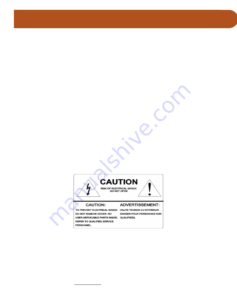
The lightning flash with arrowhead symbol within an equilateral triangle is intended to alert the user to 

the presence of uninsulated “dangerous voltage” within the product’s enclosure that may be of sufficient 
magnitude to constitute a risk of shock to persons. 

The exclamation point within an equilateral triangle is intended to alert the user to the presence of 

important operating and maintenance (servicing) instructions in the literature accompanying the product. 


Locate the system away from heat sources such as radiators, heat registers, stoves, or other heat 
producing products. 


Do not

 locate the system in the garage, the attic, or on any outside wall. M&S Systems recommends 

an environmentally open placement of the Central Controller for good airflow around the unit. 


Route power supply cords so they will not be walked on or pinched by items placed near them. 


Do Not

 expose the XDM4600 to moisture. Doing so can create fire or shock hazards and impair 

the warranty. 


Do not

 place the Zone Keypad (XDM46K) unit in any wall cavity with any other electrical wiring in 

the cavity. Avoid all other wiring. 

115951B.pdf   2

115951B.pdf   2

12/16/2005   8:06:45 AM

12/16/2005   8:06:45 AM

Summary of Contents for XDM4600 Xtreme Digital Music system

Page 1: ...Xtreme Digital Music System XDM4600 4 Zone 6 Source Owner s Manual ...

Page 2: ...ds Refer all servicing to qualified service personnel The lightning flash with arrowhead symbol within an equilateral triangle is intended to alert the user to the presence of uninsulated dangerous voltage within the product s enclosure that may be of sufficient magnitude to constitute a risk of shock to persons The exclamation point within an equilateral triangle is intended to alert the user to ...

Page 3: ...se only M S Systems certified replacement parts and have them installed by an M S dealer or installer Unauthorized substitutions can result in fire electric shock or other hazards Upon completion of any service or product repair have the M S Systems dealer or installer conduct a safety check to ensure that the system is in proper operating condition Unplug the Central Controller XDM46CC from the w...

Page 4: ...red IR Remote XDM46R 6 Door Station DS3B2 9 Installing the XDM4600KIT 10 Introduction 10 Safety Instructions 10 Basic Planning 10 Installing the Central Controller 13 Installing the Audio Sources and IR Emitters 14 Installing the Zone Keypads 16 Installing the Speakers 18 Installing the Door Station 18 Installing the Expansion Hub 19 Installing a Local Audio Source Wall Plate 22 M S Systems 2 Year...

Page 5: ...ones 10 Figure 5 Sample House Plans for XDM4600KIT Installation 8 Zones 11 Figure 6 Central Controller Wiring 12 Figure 7 XDM4600KIT Wiring Scheme 13 Figure 8 Wiring for Audio Sources and IR Emitters 15 Figure 9 Zone Keypad Rough In 16 Figure 10 Zone Keypad Wiring 17 Figure 11 Door Station Wiring 19 Figure 12 Back of the Expansion Hub 20 Figure 13 4 Zone Expansion Hub Wiring 21 Figure 14 Optional ...

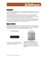
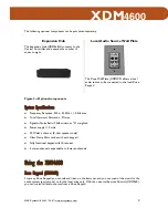
Page 6: ...es any music and intercom function that is playing so the chime can be heard over the speakers in each zone Each zone is powered from the Central Controller requiring only one power cable to go from a house outlet to the system System Overview The XDM4600 provides six audio sources to four zones or rooms in the home In addition the Zone Keypads and the Door Station have intercom functions page all...

Page 7: ...IRE connect the Central Controller IR output to the audio equipment IR eye so the IR Remote can be used to control that equipment from the Zone Keypads Extra emitters can be purchased in packages of six Door Station The Door Station DS3B2 is installed at the front door and is used as an intercom for communication with visitors The system accommodates one Door Station only The Door Station requires...

Page 8: ...ations Frequency Response 20hz 20KHz 0 5db max Total Harmonic Distortion 2 max Signal to Noise Ratio 95db minimum A weighted Power supply 110 volts 30 Watts a channel 8 ohm speakers only Class D amplifiers reside with each keypad Fully functional keypad with IR receiver 4 stereo channels expandable to 8 stereo channels Using the XDM4600 Zone Keypad XDM46K From any Zone Keypad you can talk and list...

Page 9: ...sic at a local zone only press and release in less than 3 seconds the POWER button All music is turned off for the local zone The intercom continues to function Volume Music and intercom volume are independent of one another and are controlled separately Music Volume The volume buttons on the Zone Keypad control the volume for that keypad only To adjust the music volume press VOLUME UP or VOLUME D...

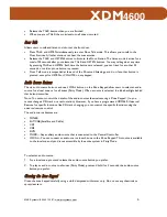
Page 10: ...low users to select an audio source for a local zone or for all zones Party Mode When a source is selected the blue backlight behind that button intensifies Note You cannot control the details of the audio sources themselves using a Zone Keypad i e you cannot change a CD track or a radio station However if you have a programmed XDM46R Universal Remote for specific functions like CD track changing ...

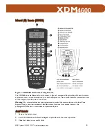
Page 11: ...en the IR Emitters are installed from a Zone Keypad in another area of the house Warning The volume buttons are preprogrammed to control the music volume on the local Zone Keypad If you go into learn mode and transfer volume functions from another remote this preprogrammed function is overridden and permanently lost Install Batteries 1 Remove the battery cover 2 Insert 4 AAA batteries Follow the d...

Page 12: ... blinking 2 Press the device button of the audio source you want to transfer a signal for 3 Press a storage button This is the button that will be used to perform the signal you transfer The word LEARN stops blinking The unit is now prepared to accept input from the original remote 4 Place the original remote so that its infrared beam points at the bottom end of the XDM46R The two remotes should b...

Page 13: ... Refer to the instructions that came with the XDM46R to see a list of the available characters Program Macros You can program macros into the XDM46R to perform a series of functions with just two key presses MACRO assigned Storage or Device button Each macro can be programmed to perform up to 20 steps To program a macro 1 Press the LEARN button on the back of the remote Use a paperclip or similar ...

Page 14: ...utton on the back of the remote Use a paperclip or similar tool to press the button 2 Press the audio source button storage key or macro program you want to clear If no button is pressed within 15 seconds the remote exits Clearing Stored Data mode Reset the Remote Press the RESET button on the back of the XDM46R Use a paperclip or similar tool to press the button After reset all data remains but t...

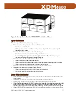
Page 15: ...ased separately If you follow the step by step illustrated instruction in this section the result will be a successful professional quality installation If you need help with troubleshooting please call our technical staff at 1 800 366 9422 Safety Instructions Before you begin installing the XDM4600 please read the important safety instructions on page i Basic Planning Possible System Configuratio...

Page 16: ...ents or other heat sources located near the Controller Make sure there are no obstructions to wiring in the wall cavity Determine where the zone line level input output wall plate will be located Determine how wiring will be routed to each location Make sure you avoid wiring for 120 240V security dimmers etc Plan so the length of wiring can be kept to a minimum System Wiring Considerations Use bot...

Page 17: ...ation port or the Zone power cable from being plugged into the Zone speaker port Do not staple wires Stapled wires can cause shorts Also if a wire has been cut too short at one end stapling makes it impossible to pull additional wire through the wall Do not splice wires Splices are unreliable and defeat the signal isolation properties of the wires Keep all system wires away from objects such as he...

Page 18: ...ng the Central Controller to the Zone Keypads and the Door Station 16 gauge 2 conductor power wire is shown connecting the Central Controller to the Zone Keypads and 18 guage 2 conductor speaker wire connecting the Zone Keypads to their speakers At the top of the Central Controller the line going from the Central Controller in the direction of the Expansion Hub represents the connection cable Inst...

Page 19: ...the Zone CAT 5 wires with the Door Station CAT 5 wires Knot or fasten all wires in some manner to prevent them from slipping out through the back of the electrical box located at the wall port Wiring Considerations See Figure 6 for a detailed illustration of the back of the Central Controller Attach the 16 gauge 2 conductor power wiring to the removable power connector as indicated on the connecto...

Page 20: ...e audio sources to the Central Controller Line level audio cables carrying audio out from the Central Controller are shown connecting the Central Controller to the tuner audio component The Emitters are plugged into the IR Emitter ports on the back of the Central Controller as shown in Figure 8 Connect each IR Emitter cable to the corresponding IR output on the back of the Central Controller Remov...

Page 21: ...s Figure 9 Zone Keypad Rough In image shows 1 16 gauge 2 conductor power wire 2 18 gauge speaker wire and 2 CAT 5 cables one for communication and the second for local source Keep all Zone Keypad wiring away from 120 240V wires dimmers and other control wiring The 16 gauge 2 conductor wire for power supply and 18 gauge 2 conductor speaker wire enter the electrical box on the left side when you are...

Page 22: ...nector attaches to the two CAT 5 cables On the label a heavy black line separates the connection of the two wires Any unused wires are cut off Refer to the connector label for the proper position of each color coded wire From top to bottom the color code is as follows blue white blue green orange brown and brown white This group is for the CAT 5 cable that goes to the wall plate The remaining colo...

Page 23: ...s in air return cavities or in walls that contain plumbing Place in wall speakers six to eight feet apart but no closer than two feet to any adjacent wall or ceiling Do not place in wall speakers in the same stud space as in wall speakers for other zones Ceiling speakers should be spaced six feet apart for eight foot ceilings and eight feet apart for ten foot or greater ceilings Place them no clos...

Page 24: ...ponent It expands your system to eight zones Location Considerations Do not place anything on top of the Expansion Hub that will interfere with the airflow out of the vents Do not place the Expansion Hub near any strong heat source such as a heating vent or a heating element Place the Expansion Hub on top of the Central Controller Because the Expansion Hub has feet you can stack it on top of the C...

Page 25: ...of the electrical box located at the wall port Wiring Considerations Attach the Expansion Hub cable from the Central Controller to the Expansion Hub Attach the 16 gauge 2 conductor power wiring to the removable power connector as indicated on the connector label and as shown in the wiring connection detail Attach the CAT 5 wires to the removable zone connectors as indicated on the connector label ...

Page 26: ... wire From right to left the color code is as follows orange orange white green and green white Figure 13 4 Zone Expansion Hub Wiring Figure 13 shows the system wiring for the Expansion Hub XDM46EH and four Zone Keypads XDM46K and their speaker pairs How to read the schematic CAT 5 cables are shown connecting the Expansion Hub to the keypads and the keypads to the local audio source wall plates Re...

Page 27: ...cavities that contain 120 240V appliance wiring or within 18 inches of fluorescent lighting dimmers security wiring and other control wiring The wall plate is installed in a single gang electrical box The wall plate uses a CAT 5 cable to connect to the keypad Do not place Wall Plates in air return cavities or walls that contain plumbing Place Wall Plates within six feet of the Zone Keypad The Wall...

Page 28: ...or fitness for a particular purpose or otherwise and of any other obligations or liability on the seller s part This limited warranty does not cover damage caused by improper installation acts of God criminal acts the violation of applicable building or electrical codes or the use of non M S wire cable excluding CAT 5 and RG 6 or wall housings Under no circumstances shall M S Systems be liable for...

Page 29: ...M S Systems 800 421 1587 www mssystems com 24 XDM4600 115951 B ...

Page 30: ...le DMC1 User Manual Subject Author Jo Francis Byrd Keywords Comments Creation Date 12 5 2005 3 03 PM Change Number 4 Last Saved On 12 16 2005 8 03 AM Last Saved By kayc Total Editing Time 20 Minutes Last Printed On 12 16 2005 8 03 AM As of Last Complete Printing Number of Pages 29 Number of Words 6 316 approx Number of Characters 36 004 approx ...

Reviews: