background image

OPERATING INSTRUCTIONS

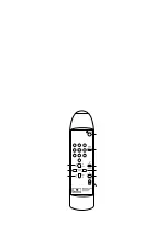
CONTROL BOX AND REMOTE CONTROLLER

The control box is the "heart" of the system. It supplies power to the motorised expans and executes commands from

the remote controller. The control box display shows the current background number. Only the currently selected

background may be rolled up or down at any given time.

Control box plugs and connectors:

Ten expan power supply plugs (24V DC 6A max.) - allows up to 10 motorised expans to be connected and

controlled

RS232 standard PC connector - enables future software upgrades and control by PC

Extension connector - enables the control box to be equipped with additional features in the future

Mains power supply socket

Before connecting the control box to the power supply, always make sure that the voltage rate specified on the control

box identification label corresponds with your local power supply and that the power supply cable complies with local

safety standards!

Switch off the control box. Plug the 6,3 mm jack of the motorised expan into one of the ten expan sockets on the

control box. Make sure that the jack is fully inserted into the socket. The motorised expan is immediately

ready to use.

!

!

!

!

Never connect the control box to any equipment that is not a part of Manfrotto's motorised

expan background support system. This may lead to a system damage or injury to users.

C

C

ONNECTING THE CONTROL BOX TO THE POWER SUPPLY

ONNECTING MOTORISED EXPANS

T 6,3A

RS

232

EXT

.

WARNING!

DISCONNECT

FROM

M A

I N

S

S U

P P

L Y

B E

F O

R E

R E

M O

V I

N G

T H

E

C O

V E

R !

POWER

RA

TING

:

A

C 230V

50Hz

00001-2

SERIAL

N

:

°

100W

MAX

.

MADE

IN

POLAND

MAINS

PRO

TECTION

:

T

0,7A

Display

IR sensor

Motor fuse

Power supply socket

Mains fuse

On/Off switch

RS-232 Connector

“Extension” connector

ID label

Motorised expan

sockets

Fig. 4 Control Box

7

Summary of Contents for 851

Page 1: ...INSTRUCTIONS MOTORISED EXPAN BACKGROUND SUPPORT SYSTEM 851 852 850 854 4 854 6 854 10...

Page 2: ......

Page 3: ...able stop levels for each background Advanced motor electronics protect against overload short circuit over voltage and electrostatic charge Internal software upgrades are possible via PC Customisable...

Page 4: ...g components control box with remote control unit mounting bracket and this manual several sets of motorised expans each set comprises one motorised and one passive expan one pair of background holder...

Page 5: ...fix the holders as level as possible otherwise the backgrounds will not roll straight this may lead to background damage Make sure to not exceed maximum specified load for each holder Always use screw...

Page 6: ...ply switch on the bottom side of the control box 2 Install the supplied batteries in the remote controller Follow the diagram inside the remote controller to insert the batteries in correct polarity d...

Page 7: ...ntification label corresponds with your local power supply and that the power supply cable complies with local safety standards Switch off the control box Plug the 6 3 mm jack of the motorised expan i...

Page 8: ...tton on the remote controller Infra red signal reception is indicated by two LEDs at the lower right corner of each display digit To ensure optimal IR reception make sure to position the control box s...

Page 9: ...of 7 different IR frequency channels UPSEC groups or can work on a so called general channel This feature enables you to work with several different motorised background support systems in the same ro...

Page 10: ...d background whose number is shown in the control box display You can quickly choose a different background by pressing one of numbered background selection buttons 1 to 10 Additionally you can change...

Page 11: ...system is not in use Choose the background for which you want to set a new stop level Using manual roll up down buttons position the background at desired stop level high or low If you wish to set the...

Page 12: ...purposes only Motor position 1 0 0 3 0 right side 1 left side 0 test mode OFF 1 test mode ON Do not use For test purposes only Working mode 0 1 2 0 4 0 normal 1 intelli auto 2 auto UPSEC group number...

Page 13: ...1st test mode first use the number key to select the number of backgrounds you want to use then press FN and 8 buttons simultaneously Keep them pressed until you hear the long beep signal and the dig...

Page 14: ...internal protection sensors have switched the motor off Check if the motorised expan jack is inserted properly in the power supply socket Check if you are using background that is too heavy Check tha...

Page 15: ...ature range 0 C to 40 C Relative humidity 80 max Max background hanging weight 10 kg Max total background weight 20 kg Max background counterweight weight 1 kg Remote controller transmission range 10...

Page 16: ...Copyright 2003 Manfrotto Bassaon Italy Code 850 01 01 03...

Reviews: