background image

DAMPER INSPECTION

1.


Check the shaft for scratches, wear, or other obvious damage.

2.


Check the seal gland and end cap seal grooves for damage.

3.


Check shims for permanent bends or damage.

4.


Check all other parts for obvious damage, replace if necessary.

5.


Replace all seals that have been removed.

FORK INSPECTION

1.


Check the fork boots for obvious damage.

2.


Check the dust seal for tears, wear, or damage.  Replace if needed.

3.


Inspect the lower and upper bushing for damage to the Teflon coating.  Replace using the bushing removal and replacement kit
if necessary.

4.


Check all MCU & springs for obvious damage.  Replace if necessary.

5.


Check the prelude adjuster and connectors.  Replace if damaged.

6.


Check the outer leg/arch assembly for nicks or deep gouges on outside and inside.  Replace if damaged.

7.


Check the inner leg for deep gouges and other obvious damage.  Minor wear resulting in color change is not detrimental to the
gold anodize surface.  Replace if wear is excessive or damaged.

8.


Check inner legs at the bottom of the crown for cracks or for flaking anodize.  Replace crown steer leg assembly if cracked or if
gold anodize is beginning to flake.

9.


Check the underside of the crown for cracks.  Replace if cracked.

RE-ASSEMBLY
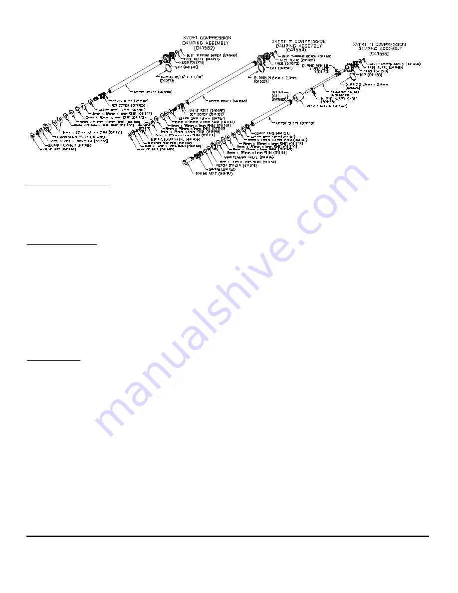
Lower Shaft Figure 11:

1.


Install all o-rings and seals removed.

2.


Grease all seals lightly with a seal grease.

3.


Apply small amount of blue loctite to piston seat threads.

4.


Assemble shim stack and spacers inexact order that they were removed.  For  XVERT & XVERT R , thread on valve nut and
torque 30 IN-LB (3.5 N-m) max.  For XVERT TI hand tighten piston seat.  Be sure large blow off washer will slide over piston
spacer and compress the  small small spring.  Clamp shaft in soft jaws or collet and line up slots in clamp ring with hole in
piston seat using 1/8Ó or smaller pin.  Use a 5mm allen wrench and tighten piston seat by turning allen wrench and pin at the
same time.  Torque 30 IN-LB (3.5N-m) max.

5.


XVERT TI install lower needle gently into shaft, thread until it stops then back off one turn for initial adjustment.

6.


Slide shaft assembly through the plastic end cap, place detent ball in place and slide 2

nd

 stg Elastomer.

7.


Insert into left leg and thread in end cap.  Torque 30 IN-LB (3.5N-m) max.

8.


Add approximately 100CC of 5WT Maxima or equivalent oil.  Do not over fill.  Check oil level, see Figure 8.

Compression Damping Assembly Figure 12:

1.


Reassemble compression damping stack following the instructions above for the lower shaft assembly.

2.


Install compression damping assembly into the leg.  The oil level should cover the compression valve when the assembly is
installed.

Page 9

Compression Rod & Boots Figure 13:

1.


Clean all parts thouroughtly.

Summary of Contents for 98 XVERT

Page 1: ...ny other alterations or modifications to your fork should be considered unsafe Contact Answer Products Technical Support prior to modifying your fork in any way for safety information 4 Do not use any Manitou Fork if any parts appear to be broken bent cracked or damaged Contact your dealer or Answer Products Technical Support 800 670 7446 if you have any questions concerning the integrity or condi...

Page 2: ...f frame 7 Install upper bearings spacers and stem 8 Install stem cap and screw tighten until slack just disappears 9 Install handlebars to desired height Torque stem handlebar pinch screws and stem clamping system to manufacturerÕs instructions 10 Install brakes and adjust per manufacturers instructions Note All 98 Manitou Forks Forks are equipped with a secondary catch dropout 11 Adjust front whe...

Page 3: ...BRACKET KIT 85 3674 X VERT R HAYES BUSHING KIT 85 3733 98 SOFT KIT SX SX R SX RR 85 3538 98 MEDIUM KIT SX SX R SX RR 85 3839 98 FIRM KIT SX SX R SX RR 85 3840 ADJUSTER KIT ALUMINUM SX XVERT 85 3848 98 CROWN STEER INNER LEG SET XVERT CROMOLY 85 3858 98 CROWN STEER INNER LEG SET XVERT ALUMINUM 85 3859 98 REBOUND DAMPER REBUILD KIT XVERT R 85 3864 98 REBOUND DAMPER REBUILD KIT XVERT TI 85 3865 98 COM...

Page 4: ...Page 4 ...

Page 5: ...Page 5 ...

Page 6: ...Page 6 ...

Page 7: ...ding this entire section prior to making any changes to the oil level To check the oil level remove only the compression damping assembly located in the top of the left leg Leave the right side compression stack adjuster MCU spring assembly in place to keep the fork fully extended Use a tape measure or Òdip stickÓ to determine the oil level Oil level should be between 3 5Ó 89MM and 5 75Ó 146MM bel...

Page 8: ...ut of the inner leg 3 Remove 2 nd or 3 rd Stg Elastomer and capture the 1 8Ó Dia detent ball 4 Adjuster needle must be unscrewed from the shaft 5 Remove valve nut using end wrench and holding the shaft in soft jaws or collet to prevent damage Compression Damping Disassembly figure 12 1 The compression damping assembly is almost identical to the lower shaft assembly 2 Unscrew the compression dampin...

Page 9: ...aft Figure 11 1 Install all o rings and seals removed 2 Grease all seals lightly with a seal grease 3 Apply small amount of blue loctite to piston seat threads 4 Assemble shim stack and spacers inexact order that they were removed For XVERT XVERT R thread on valve nut and torque 30 IN LB 3 5 N m max For XVERT TI hand tighten piston seat Be sure large blow off washer will slide over piston spacer a...

Page 10: ...ip snaps into the groove 5 Clean adjuster cap threads thoroughly Clean threads on inside of inner leg 6 Assemble MCUÕs springs and connectors with thick grease 7 Install adjuster assembly into inner leg just hand tight WARNING INNER FORK LEGS CROWN The inner fork legs and steer tube are press fit into the crown and may never be removed Removing them will make the fork unsafe to use If you see any ...

Page 11: ...mpression damping Try adjusting one full turn at a time To adjust XVERT TI models simply rotate the compression damping knob located on top of the left leg crown Rotating the knob clockwise will increase the damping rotating the knob counter clockwise will reduce the damping Excessive damping will give you a harsh ride over sharp bumps like rocky sections but will feel good in large hits like G ou...

Page 12: ... subjected to damping pressure A small leak in that area will not affect the performance of the fork or cause any type of damage We recommend that you store your Manitou right side up If this condition causes you some problems please contact your Answer Products dealer or call our warranty tech department for prompt service Fork is making a scraping noise that sounds as if the spring is binding Th...

Reviews: