Â
OCCASIONAL MAINTENANCE
CLEAN
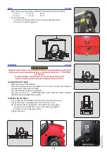
"Stationary lift truck" particle filter (Regeneration)
IMPORTANT
If the indicator lamp
comes on, contact your dealer.
If you are performing regeneration of the particle filter during the 500-hour routine servicing, replace the engine oil
after regeneration.
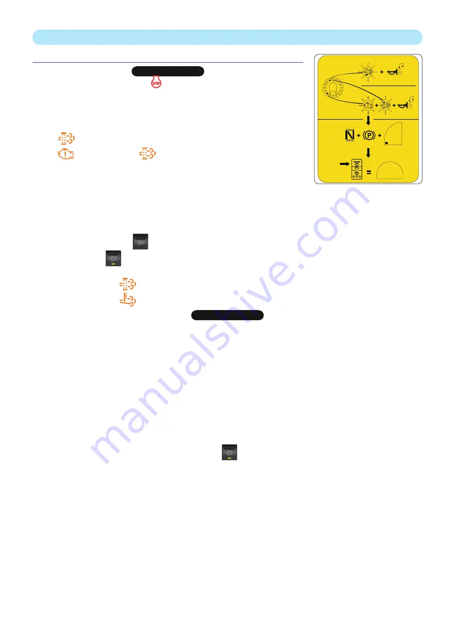
Regeneration of the particle filter is an automated procedure activated by the
operator when the following indicator lamps are displayed:
•
(slow flashing) + 2 short beeps.
•
+ 1 long beep, then
(slow flashing) + 2 short beeps.
- Check that the fuel level is sufficient.
- Park the lift truck in a safe and adequately ventilated place.
- Start the lift truck's engine.
- Check the following points:
• forward/reverse selector in neutral,
• parking brake applied,
• forks resting on the ground,
• accelerator pedal released.
- Press the top of the switch
for more than two seconds to begin the regeneration procedure.
• Indicator lamp
comes on.
• The engine speed increases.
• The indicator lamp
comes on and confirms the start of the regeneration procedure.
• The indicator lamp
comes on as soon as the particulate filter temperature is high enough.
IMPORTANT
The regeneration procedure must only be stopped if absolutely necessary.
The procedure stops automatically if the operator:
- releases the parking brake,
- presses on the accelerator pedal,
- engages forward or reverse gear,
- switches off the engine,
- presses the regeneration switch.
The time taken by the regeneration is approximately 30 minutes and varies according to various criteria, such as:
• the level of clogging of the filter,
• the engine temperature,
• the fuel quality and type of engine oil,
• the number of automatic regeneration requests cancelled,
• the ambient temperature.
At the end of the regeneration procedure, the indicator lamp
goes out and the time remaining before the next stationary
particle regeneration is reset.
3 - 34
N° 52681322
WAIT
≈ 30’
2‘’
MINI
RPM
647837 M1 (A052020)
MC 18-2/18-4 D K ST5 S1
Summary of Contents for MC 18-2 D K ST5 S1
Page 5: ...1 OPERATING AND SAFETY INSTRUCTIONS 1 1 647837 M1 A052020 MC 18 2 18 4 D K ST5 S1...
Page 6: ...1 2 647837 M1 A052020 MC 18 2 18 4 D K ST5 S1...
Page 7: ...1 3 647837 M1 A052020 MC 18 2 18 4 D K ST5 S1...
Page 25: ...2 DESCRIPTION 2 1 647837 M1 A052020 MC 18 2 18 4 D K ST5 S1...
Page 26: ...2 2 647837 M1 A052020 MC 18 2 18 4 D K ST5 S1...
Page 71: ...2 47 647837 M1 A052020 MC 18 2 18 4 D K ST5 S1...
Page 73: ...3 MAINTENANCE 3 1 647837 M1 A052020 MC 18 2 18 4 D K ST5 S1...
Page 91: ...3 19 647837 M1 A052020 MC 18 2 18 4 D K ST5 S1...
Page 97: ...3 25 647837 M1 A052020 MC 18 2 18 4 D K ST5 S1...
Page 105: ...3 33 647837 M1 A052020 MC 18 2 18 4 D K ST5 S1...
Page 112: ...3 40 647837 M1 A052020 MC 18 2 18 4 D K ST5 S1...
Page 113: ...4 OPTIONAL ADAPTABLE ATTACHMENTS FOR THE RANGE 4 1 647837 M1 A052020 MC 18 2 18 4 D K ST5 S1...
Page 114: ...4 2 647837 M1 A052020 MC 18 2 18 4 D K ST5 S1...
Page 116: ...4 4 647837 M1 A052020 MC 18 2 18 4 D K ST5 S1...
Page 119: ...ATTACHMENTGUARDS FORK GUARD PART NO 227801 4 7 647837 M1 A052020 MC 18 2 18 4 D K ST5 S1...
Page 120: ...4 8 647837 M1 A052020 MC 18 2 18 4 D K ST5 S1...


