(05/06/2012)
10-06-M184EN
10
12
ENGINE REMOVAL
2
3
1
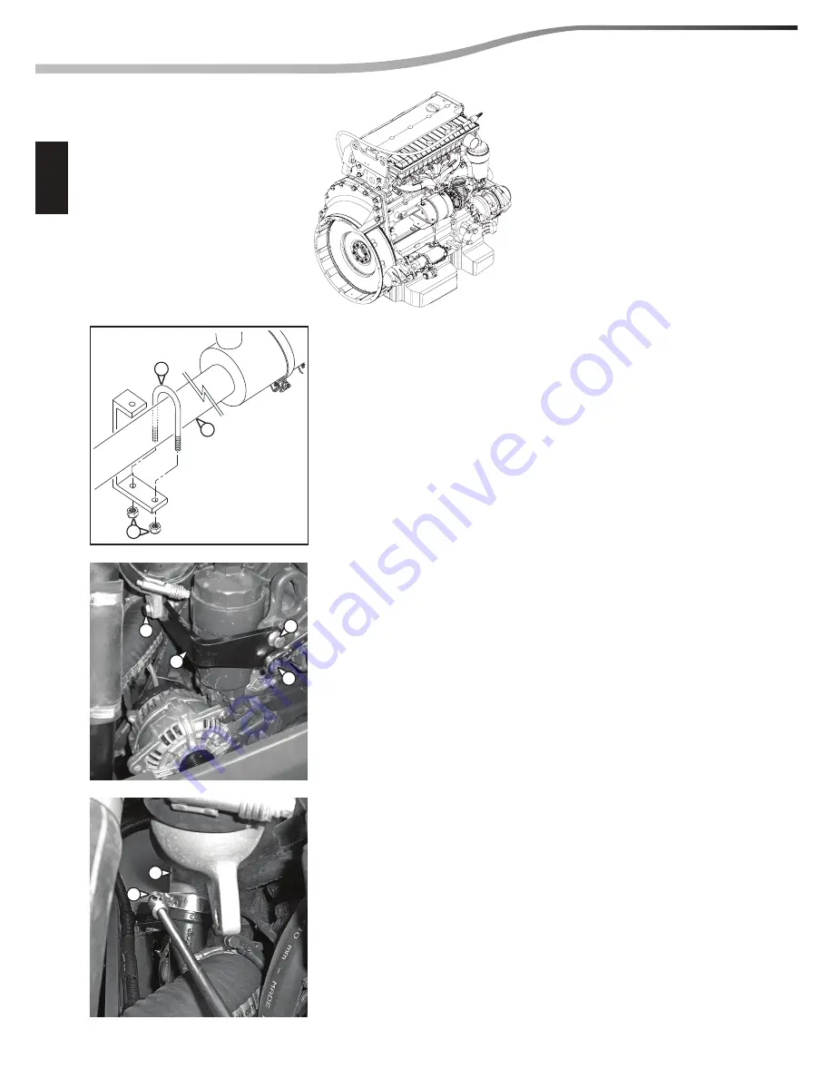
G - REMOVING THE TURBOCOMPRESSOR
Slacken the 2 nuts (Ref. 1) and remove the 2 brackets (Ref. 2)
which secure the air suction duct (Ref. 3).
Slacken the screws (Ref. 4 and 5) and remove the bracket (Ref. 6).
Slacken the clamp (Ref. 7) and remove the hose (REf. 8).
b
Fit caps on all the ducts to prevent foreign bodies from
entering the circuits.
5
6
8
7
4
4
Summary of Contents for MHT 10225
Page 4: ...GENERAL INSTRUCTIONS AND SAFETY NOTICE GENERAL CONTROL AND ADJUSTMENT GENERAL 00...
Page 5: ......
Page 12: ...00 04 M184EN GENERAL CONTROL AND ADJUSTMENT pages STANDARD TIGHTENING TORQUES 2 05 06 2012 00...
Page 15: ......
Page 16: ...05 06 2012 10 03 M184EN 10 ENGINE COMPONENTS LOCATION page MERCEDES ENGINE 2...
Page 19: ...05 06 2012 10 03 M184EN 10 4 ENGINE COMPONENTS LOCATION...
Page 47: ...05 06 2012 10 06 M184EN 10 26 ENGINE REMOVAL...
Page 73: ......
Page 79: ...06 03 2012 110 01 M184EN 110 6 OPTIONS ATTACHMENTS CHARACTERISTICS AND SPECIFICATIONS...
Page 81: ...07 03 2012 110 03 M184EN 110 2 OPTIONS ATTACHMENTS COMPONENTS LOCATION...
Page 89: ...110 07 03 2012 110 03 M184EN 10 OPTIONS ATTACHMENTS COMPONENTS LOCATION...
Page 101: ......
Page 103: ...06 06 2012 20 02 M184EN 20 2 TRANSMISSION SCHEMATIC DIAGRAMS...


