(07/03/2012)
110-04-M184EN
110
7
OPTIONS - ATTACHMENTS CONTROL AND
ADJUSTMENT
To switch off the unit, press the «Fan speed reduction command» button (Ref. 8) to deactivate the fan
completely; to switch it back on again, press the «Fan speed increase command» button (Ref. 7).
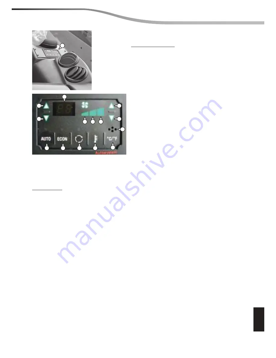
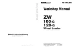
A - Control unit
Legend of functions:
1 -
Decrease internal temperature
2 -
Increase internal temperature
3 -
Temperature indicator setting
4 -
Indicator 1
a
fan speed
5 -
Indicator 2
a
fan speed
6 -
Indicator 3
a
fan speed
7 -
Fan speed increase command
8 -
Fan speed decrease command
9 -
Internal air temperature sensor
10 -
°C / °F conversion and vice versa
11 -
External temperature reading command
12 -
Recirculation command
13 -
Compressor exclusion
14 -
Automatic function reset
ERROR CODES
In case of a fault that aff ects the automatic regulation, the control unit displays an error code consisting
of the letter
E
followed by a number which identifi es the type of fault according to the following Table::
E 1
external air temperature sensor (E.T.) interrupted.
E 2
external air temperature sensor (E.T.) short circuit..
E 3
cab air temperature sensor (I.T.) interrupted..
E 4
cab air temperature sensor (I.T.) short circuit.
E 5
mixed air temperature sensor (M.T.) interrupted.
E 6
mixed air temperature sensor (M.T.) short circuit.
Since automatic regulation is not possible, the keys for increasing and decreasing the internal temperature
are used to change the position of the mixer, while the fan speed is fi xed at the 2
a
speed.
If the error is solved, the control unit resumes normal operation only after resetting the + key.
A
1
2
3
4
5
6
7
8
14
13
12
11
10
9
Summary of Contents for MHT 10225
Page 4: ...GENERAL INSTRUCTIONS AND SAFETY NOTICE GENERAL CONTROL AND ADJUSTMENT GENERAL 00...
Page 5: ......
Page 12: ...00 04 M184EN GENERAL CONTROL AND ADJUSTMENT pages STANDARD TIGHTENING TORQUES 2 05 06 2012 00...
Page 15: ......
Page 16: ...05 06 2012 10 03 M184EN 10 ENGINE COMPONENTS LOCATION page MERCEDES ENGINE 2...
Page 19: ...05 06 2012 10 03 M184EN 10 4 ENGINE COMPONENTS LOCATION...
Page 47: ...05 06 2012 10 06 M184EN 10 26 ENGINE REMOVAL...
Page 73: ......
Page 79: ...06 03 2012 110 01 M184EN 110 6 OPTIONS ATTACHMENTS CHARACTERISTICS AND SPECIFICATIONS...
Page 81: ...07 03 2012 110 03 M184EN 110 2 OPTIONS ATTACHMENTS COMPONENTS LOCATION...
Page 89: ...110 07 03 2012 110 03 M184EN 10 OPTIONS ATTACHMENTS COMPONENTS LOCATION...
Page 101: ......
Page 103: ...06 06 2012 20 02 M184EN 20 2 TRANSMISSION SCHEMATIC DIAGRAMS...


