42
2
MRT 1850 - 2150
M
S
Series
FR
EN
ES
4
4
4
4
-
-
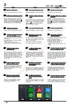
CONTROL PANEL FOR
SAFETY AND DEVICE
Components location on the machine
The sensors are positioned on the boom
and cylinders in order to detect data
when working, while the main unit and
the control panel are located inside the
cabin.
1 - Length/Angle sensor: on the left side
of the boom
2 - Nr. 4 Pressure Transducers: on Main
and Compensation cylinders.
3 - Control Panel: in the cabin.
4 - Main Unit: in the cabin.
5 - Red lamp off the safety device.
4
4
4
4
-
-
PUPITRE DE MANDO PARA
DISPOSITIVO DE SEGURIDAD
Posicionamiento de los componentes
del limitador en la máquina
Los dispositivos de marcación están ubi-
cados en la estructura de la máquina
para registrar los datos durante el traba-
jo; la unidad central y el cuadro de man-
dos se encuentran en la cabina, a dis-
posición del operador.
1 – Sensor de ángulo y desfile a la
izquierda del brazo.
2 – 4 transductores de presión : en los
cilindros de elevación y
compensación.
3 – Cuadro de mandos: en cabina.
4 – Unidad central: en cabina.
5 - Intermitente rojo
4
4
4
4
-
-
TABLEAU DE CONTROLE DU
DISPOSITIF DE SECURITE
Positionnement sur la machine des
elements du cec
Les Capteurs sont installées sur la
structure de la machine pou en mesurer
les données en phase de travail, tandis
que l'Unité Centrale et l'Afficheur se
trouvent en cabine, à disposition de
l'Opérateur.
1 - Capteur Angle/Longueur: sur le coté
gauche du bras
2 - 4 Capteurs de pression:sur les vérins
de soulèvement et de compensation
3 - Afficheur: en cabine
4 - Unité centrale: en cabine
5 - Feu clignotant rouge
1
2
3
4
5
44
Summary of Contents for MRT 1850 Turbo M Series
Page 1: ......
Page 9: ......
Page 44: ......
Page 97: ......
Page 115: ...6 6 5 4 5 4 6 6 6 6 5 4 5 4 6 6 4 5 6 6 B13 2 MRT 1850 2150 MS Series 18 3 FR EN ES B13 1...
Page 142: ...4 4 I IN NS ST TA AL LL LA AT TI IO ON N S SY YS ST TE EM MS S S SI IS ST TE EM MA A...
Page 143: ......
Page 207: ......
Page 215: ......


