3-82
IT
EN
DE
IT
EN
DE
H10 - Maintenance/troubleshooting on
radio control (optional)
In case of radio connection problems with
the radio control system, contact the dea-
ler (after making a note of all the indica-
tions given on the radio control label).
Only the manufacture can attribute the
frequencies. If this rule is not respected,
right to the warranty is lost.
SIGNALS ON THE PUSHBUTTON PANEL
T
he status and alarm indications are shown
by the pushbutton panel by means of the
MICRO green LED,
the red LED ON, and the built-in warning
sound signal.
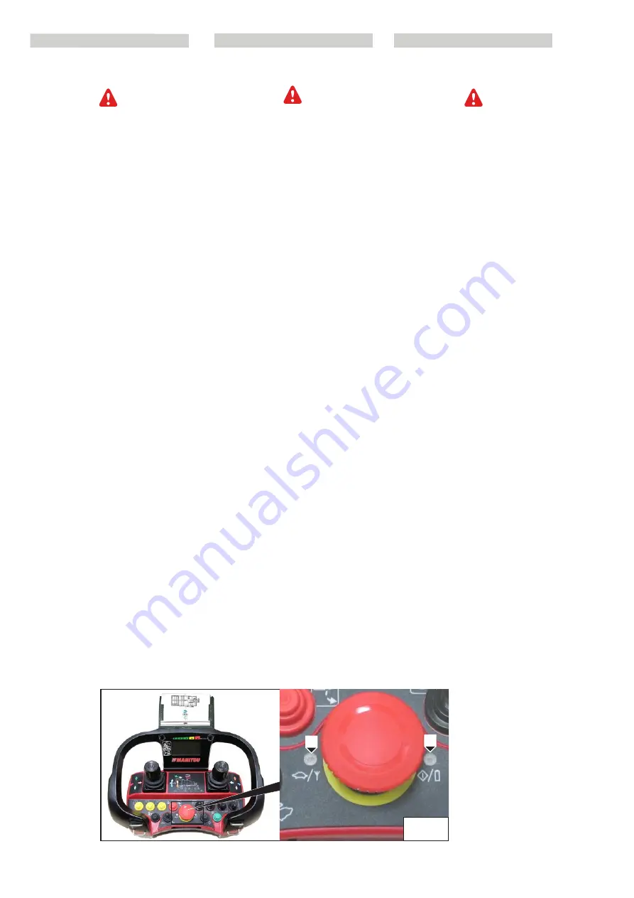
- MICRO LED; to the LH of the stop button
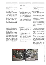
1 (Fig. H10/1)
- LED ON; to the RH of the stop button 2
(Fig. H10/1)
- SOUND; by means of internal warning
sound
Indications of the operating status
The pushbutton panel uses the LED ON and
MICRO LED to indicate the current opera-
ting status and alarms.
Red LED ON;
the pushbutton panel is active
and is transmitting data to the central unit
via radio.
Red LED which flashes once every second;
the battery is running out.
This indication is preceded by three war-
ning sounds emitted by the internal buzzer.
MICRO green LED which flashes once,
twice, thrice, four or five times every
two seconds;
the percentage hydraulic
movements speed set are active.
2
1
H10/1
H10 -
Manutenzione/ricerca guasti sul
radiocomando (optional)
In caso di problemi di collegamento radio
con il sistema del radiocomando, è possi-
bile contattare il concessionario (munen-
dosi prima di tutte le indicazioni ripor-
tate sull’etichetta del radiocomando).
L’attribuzione delle frequenze viene fatta
esclusivamente dal costruttore. Non atte-
nersi a questa regola farà perdere il diritto
alla garanzia.
SEGNALAZIONI DELLA PULSANTIERA
Le indicazioni di stato e di allarme sono
segnalate dalla pulsantiera tramite il LED
verde MICRO, il LED rosso ON e attraverso il
segnale acustico incorporato.
-
LED MICRO; a sinistra del pulsante d’arres-
to 1 (fig. H10/1)
- LED ON; a destra del pulsante d’arresto 2
(fig. H10/1).
-
SUONO; tramite segnale acustico interno
Indicazioni dello stato operativo
La pulsantiera utilizza il LED ON e il LED
MICRO per indicare lo stato di funzionamen-
to attuale e gli allarmi.
LED rosso acceso;
la pulsantiera è attiva
e sta trasmettendo i dati all’unità centrale
via radio.
LED rosso che lampeggia una volta ogni
secondo
; la batteria si sta esaurendo.
Questa indicazione è preceduta da tre seg-
nali acustici emessi dal buzzer interno.
LED verde MICRO che lampeggia uno,
due, tre, quattro o cinque volte ogni due
secondi
; il set di velocità movimenti idrauli-
ci percentuali sono attivi.
H10 -
Wartung/Fehlersuche auf
Funksteuerung (Optional) ausführen
Bei Verbindungsproblemen zwischen Radio
und Funksteuerung den Vertragshändler
kontaktieren (zuerst alle Angaben auf
dem Etikett der Funksteuerung able-
sen). Die Frequenzzuordnung wird aus-
schließlich vom Hersteller ausgeführt. Bei
Nichtbeachtung dieser Regel erlischt die
Garantie.
SIGNALISIERUNGEN AUF DER
SCHALTTAFEL
Zustandsanzeigen und Alarmmeldungen
können von der Schalttafel mit der grünen
LED MIKRO und der roten LED EIN sowie
durch das eingebaute akustische Signal sig-
nalisiert werden.
-
LED MIKRO; links von der Stopptaste 1
(Abb. H10/1)
- LED EIN; rechts von der Stopptaste 2 (Abb.
H10/1).
-
TON; mittels internem akustischem Signal
Angabe des Betriebszustandes
Die Schalttafel zeigt mit der LED EIN
und mit der LED MIKRO den aktuellen
Betriebszustand und die Alarmmeldungen
an.
Rote LED Ein;
die Schalttafel ist aktiv
und überträgt über Funk Daten an die
Zentraleinheit.
Wenn die rote LED ein Mal pro Sekunde
blinkt
, ist die Batterie fast leer.
Vor diesem Blinkvorgang gibt der interne
Summer drei akustische Signale ab.
Grüne LED MICRO, die 1, 2, 3, 4 oder 5 Mal
alle zwei Sekunden blinkt
; die prozentua-
len Geschwindigkeiten der hydraulischen
Bewegungen sind aktiv.
649050
IT-EN-DE
(01/06/2017)
MRT
EASY
55P
400
ST4
S2,
MRT
EASY
55P
360
ST4
S2,
MRT
EASY
75P
400
ST3B
S2,
MRT
EASY
75P
360
ST3B
S2,
MRT-X
EASY
75P
400
ST3A
S2,
MRT-X
EASY
75P
360
ST3A
S2


