3-14
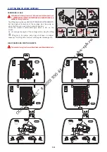
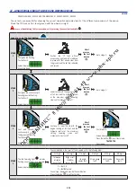
Long press on the test button.
STAGE
1
1
- First green led flashing.
- Test button lit.
- Screen display.
TEST MODE 1/3
- An audible beep.
- Position the lift truck without
accessories, right and left stabilizers
in place with front wheels clear from
the ground and the jib fully retracted
and raised.
Short
press on
the test
button
.
- Go to stage 2.
STAGE
2
2
1
- First green led continuously lit.
- Second green led flashing.
- Test button lit.
- Screen display.
TEST MODE 2/3
- Lower the jib with the engine running
at full revs and the hydraulic control
at the maximum setting. Lowering
slows until movement iscut-off.
Short
press on
the test
button
.
- Go to stage 3.
STAGE
3
3
1
2
- First and second green leds
continuously lit.
- Third green led flashing.
- Test button lit.
- Screen display.
TEST MODE 3/3
- Continue to lower the jib with the
engine running at full revs and the
hydraulic control at the maximum
setting. Lowering slows until
movement is next cut-off.
Short
press on
the test
button
.
TEST OK
- First 5 leds lit.
- Screen display.
TEST OK
- Press the button
to exit test mode.
TEST NOT OK
- See stage 4.
STAGE
4
- The fault warning light
remains
flashing on until the error is repaired.
- Screen display.
TEST NOK
1 0 1 0 0 1
- The combination is the result of tests carried out in the following order:
1st digit
2nd digit
3rd digit
4th digit
5th digit
6th digit
Telescope
retracted
sensor fault.
Right or left
stabilizer
sensor fault.
Jib angle
sensor fault.
Strain gauge
fault.
Safety valve
fault.
Governing
fault.
1 = Test OK
0 = Faultdetected
- Consult your dealer and provide the combination.
- Press the button
to exit test mode.
A7 - LONGITUDINAL STABILITY LIMITER AND WARNING DEVICE
CHECK
FROM MACHINE N°: 590613 AND FOR MACHINES N°: 589029 ; 589122 ; 589165
- These tests are essential for checking the correct operation and adjustment of the different components of the device.
- Place the lift truck on flat, level ground with the wheels straight.
In case of doubt during the test procedure, exit by pressing the cancel button briefly
.
Summary of Contents for MT 1058 R PRIVILEGE
Page 1: ......
Page 3: ......
Page 4: ...1 1 1 OPERATING AND SAFETY INSTRUCTIONS...
Page 5: ...1 2...
Page 31: ...1 28...
Page 32: ...2 1 2 DESCRIPTION...
Page 33: ...2 2...
Page 44: ...2 13...
Page 74: ...2 43...
Page 78: ...3 1 3 MAINTENANCE...
Page 79: ...3 2...
Page 84: ...3 7...
Page 92: ...3 15...
Page 104: ...3 27...
Page 116: ...4 1 4 OPTIONAL ATTACHMENTS FOR USE WITH THE RANGE...
Page 117: ...4 2...
Page 119: ...4 4...
Page 129: ...4 14...
Page 130: ...5 1 5 SPECIFIC CANADA...
Page 131: ...5 2...
Page 132: ...5 3 TABLE OF CONTENTS DIMENSIONS AND LOAD CHART MT 1058 R PRIVILEGE 5 4...
Page 135: ...5 6...
Page 136: ...6 1 6 SPECIFIC AUSTRALIA See also the operator s manual supplement 647065 AU...
Page 137: ...6 2...
Page 139: ...6 4...

